During the actual machining process, the cutting depth, feed rate, and spindle speed are predetermined and kept constant throughout the cutting process. Therefore, it is essential to optimize the combination of factors affecting surface roughness to obtain the optimal surface quality value. This article begins with the calculation formula of surface roughness and its relationship with chip thickness. It further explores the relationship between surface roughness, cutting depth, and feed rate. Additionally, it examines the impact of various factors on surface roughness through experimentation.
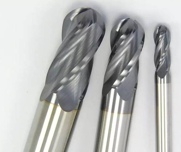
Mechanism of Surface Roughness Generation
Mechanism of Residual Height Generation
In curved surface machining, the residual height is mainly formed by the tool moving along the tool path and leaving material on the surface of the workpiece unremoved. As shown in Figure 1, the following parameters are defined: P as the tool contact point, R as the radius of the curved surface, θ as the angle between two radius lines, and n as the normal vector at point P. The stepover distance is represented by d, and it is closely related to the residual height h. Based on Figure 2(a), we can derive the following relationship:
![]()
In the equation: r represents the tool radius, and kh represents the normal curvature of the machining surface along the cutting feed direction.

When using the sectional plane method to generate tool paths, calculating the normal curvature (kh) can be challenging. In practical machining, an approximation is often used, where a plane approximates the surface between two adjacent tool paths, as shown in Figure 2(b). The stepover distance is considered the normal distance between the sectional planes. In this case, the residual height (h) can be described by the following equation:
![]()
1.2Calculation of Surface Roughness
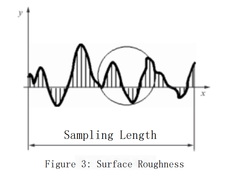
Due to the presence of residual height, the surface of the part after mechanical machining will have many uneven peaks and valleys. This microscopic geometric shape is known as surface roughness, as shown in Figure 3. The parameter Ra is defined as the surface roughness, which is given by:
![]()
In the equation, L represents the sampling length.
Zooming in on Figure 3, we obtain Figure 4. When h’ is less than Y et, we can deduce:
![]() 6
6
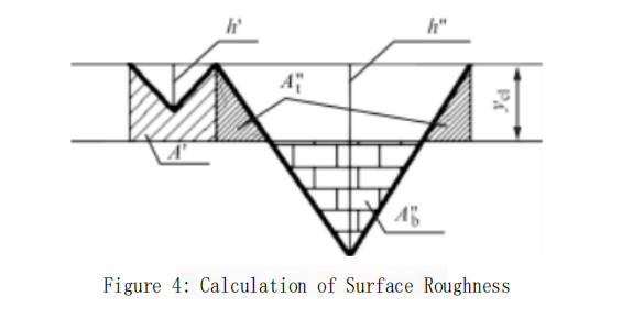
When h” is greater than Y et, we can deduce:

In the equation, E represents the area of the region. Since y_a needs to ensure that the area above and below the central line is equal, i.e.,
![]()
In equation (6), p’ and p” are weighting factors. p is closely related to the chip thickness h. After a series of derivations, we can obtain
![]()
the expression of the sampling area is as follows
![]()
In the expression:

Substituting equations (4) and (5) into equation (8), we obtain:
![]()
After substituting equation (7) into equation (9) and simplifying through calculations, the relationship between the sampling area of surface roughness and the chip thickness is obtained as follows:
![]()
According to the above equation, it can be seen that there is a very simple relationship between surface roughness and chip thickness. When milling with a ball-end cutter, the feed per tooth is constant, while the chip thickness varies continuously based on the cutting depth and feed rate.
Experimental Data and Analysis
Experimental Conditions
Under steady-state cutting conditions, by varying the cutting depth and feed rate, the surface roughness values are measured for different parameter combinations. The micro-topography of the machined surfaces is observed using a three-dimensional profilometer, and the influence of cutting parameters on surface roughness is analyzed.
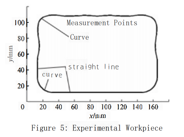
The experiment is conducted on the edge part shown in Figure 5, using a FANUC precision machining center machine. The workpiece material is 45# steel, and a high-speed steel milling cutter with a diameter of 12.5mm is selected as the cutting tool. The spindle speed is set at 800 r/min, and the cutting depth varies from 1mm to 6mm. Different feed rates are used for cutting at depths of 1mm, 2mm, 4mm, and 6mm, as illustrated in Figure 6.
Data Measurement
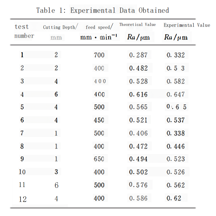
After completing the machining of the part, measurement points are selected on the curved section of the part shown in Figure 5. For each set of experimental conditions, data at these measurement points are measured twice, and the average value is taken as the experimental value. The experimental data are presented in Table 1

Data Analysis
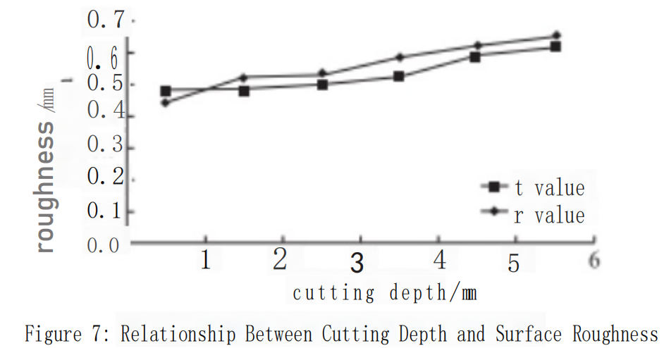
From the experimental data, it can be observed that when machining the part using a ball-end cutter and keeping the feed rate constant, the surface roughness increases with an increase in cutting depth (see Figure 7). At lower cutting depths, the surface roughness values are smaller, but excessively small cutting depths result in longer cutting times and lower processing efficiency.
Although there is a certain difference between the experimental values and theoretical values in this study, they are relatively close. Hence, the provided calculation formula in this study can be adopted. For the selected workpiece in this study, the optimum surface roughness is achieved when the cutting depth is 2mm, and the feed rate is 700mm/min.
3conclusion
The study investigated the influence of various machining parameters on surface roughness during the milling process of the workpiece. The theoretical impact of surface roughness on the surface quality of the workpiece was explored, and a theoretical calculation formula for surface roughness was derived based on its generation mechanism.
Using the trial machining method and different combinations of parameter data, the surface roughness of the machined parts was measured using a three-dimensional profilometer. The calculated theoretical values from the formula were then compared with the experimental values.
The research demonstrated that both the calculation formula and the machining method are feasible and effective in predicting and controlling surface roughness during the milling process.


