Flute number
The number of cutting edges on an end mill cutter mainly includes 2-flute, 3-flute, 4-flute, 6-flute, and other types. The number of flutes is related to the size of the chip pocket area for collecting the chips. The chip pocket is a groove for temporarily storing the chips. If we consider the rotating cylindrical profile of the end mill cutter as 100%, the chip pocket areas for various numbers of flutes are shown in the diagram below.

Proportion of the cross-sectional area of the chip holding tank
As the number of flutes increases, the chip pocket area gradually decreases while the cutting edge area increases, leading to improved rigidity. The characteristics and applications of an milling cutter depend on the number of flutes. (Refer to the table below)

Characteristics and applications of end mills with various blade numbers
Cutting edge length
When installing an mill cutter on a tool holder for machining, deflection as shown in the diagram can occur due to cutting resistance. The deflection is directly proportional to the cutting resistance and, more specifically, proportional to the cube of the length (overhang) from the end mill cutter to the tool holder.
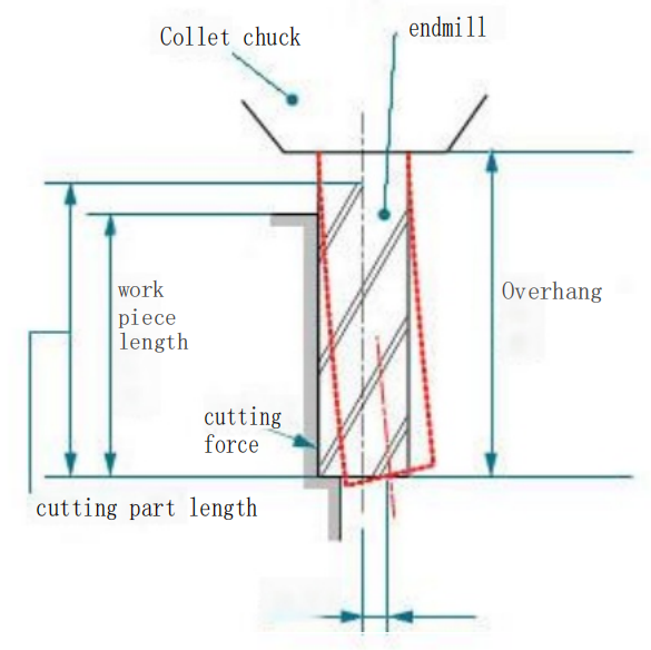
Deflection of end milling cutter
To improve the perpendicularity of the machined surface, which refers to the surface deformation of the machined surface, it is necessary to reduce deflection. This can be achieved by minimizing the overhang of the mill cutter, which means using an end mill cutter that is slightly longer than the length of the machining portion.
Therefore, the cutting edge length of a mill cutter is generally categorized as follows:
a.Extra-short
b. Short
c. Medium
d. Medium-long
e. Long
f. Extra-long
helix angle
The spiral direction of an end mill cutter is generally right-hand spiral. When using it, the rotation is in a clockwise direction when viewed from the installation side (the side of the tool holder) – this is referred to as right-hand rotation. Cutting tools that rotate in a right-hand direction are called right-hand tools, while those that rotate counterclockwise (left-hand rotation) are called left-hand tools. The mill cutters discussed in this chapter are right-hand tools with a right-hand spiral.
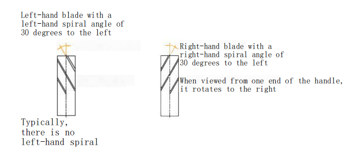
Left Blade Left Spiral Left 30 ° and Right Blade Right Spiral Left 30 °
The helix angle of a mill cutter is generally 30°. A smaller helix angle results in poorer cutting sharpness, while a larger helix angle provides better cutting sharpness. However, increasing the helix angle can also increase the axial force in the direction of tool retreat, which may lead to tool dislocation. The characteristics and applications of end mill cutters with different helix angles are shown in the table below:
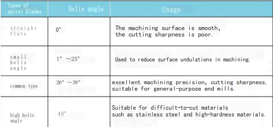
Table of Characteristics and Applications of End Mills with Different Helical Angles
Peripheral blade
The shapes, types, and characteristics of peripheral edge end mill cutters are shown in the table below:
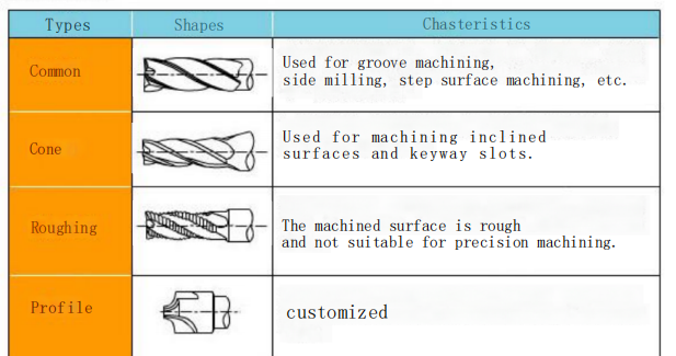
The shape of the outer edge
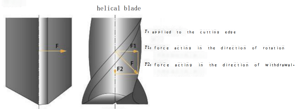
Right angle and spiral flute
cu?i c?t c?nh
The shapes, types, and characteristics of the bottom edge of a mill cutter are shown in the table below. The center cutting edges include shapes with long and short cutting edges (shown as A and C in the table) as well as twisted core shapes (shown as B in the table). They can all be used for axial feed cutting.

The purpose of each shape of end milling cutter
Hilt? of end mill
The shapes, types, and characteristics of the shank of an end mill cutter are shown in the table below:

Tool handle shape
The shapes, types, and characteristics of the neck of an end mill cutter are shown in the table below:

The shape of the handle and neck of the knife

