The calculation principle of expansion is as follows
In the process of bending, there is tension stress in the outer layer and compression stress in the inner layer. From tension to compression, there is a transition layer neutral layer. The length of neutral layer remains the same after bending as before bending, so the neutral layer is the basis for calculating the unfolding length of bending parts. The position of neutral layer is related to the degree of deformation. When the bending radius (R angle shown in the figure below) is larger and the bending angle (θ angle shown in the figure below) increases, the degree of deformation increases, the position of neutral layer gradually moves to the inner side of the bending center, and the distance between neutral layer and inner layer of sheet metal is less than 90
Calculation method:
basic formula of expansion:
Expansion length = in stock + in stock + compensation
Development length = out of stock + out of stock – compensation
Right angle bending:
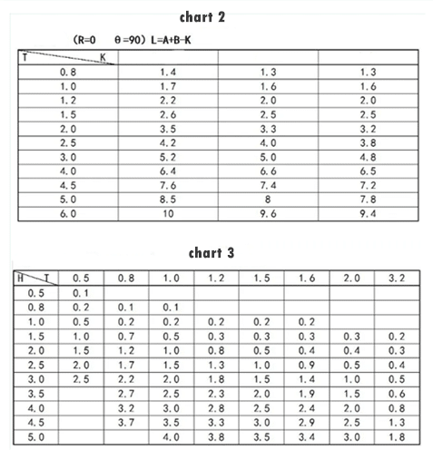
(R ≤ 2.0 θ = 90). L = a + B-K (see Table 2 for K value)
(R>2? ?θ=90)L=a+b+K
K=(R+λ)*π/2
Note: when R ≥ 5T, λ = 0.5T
When R < 5T, λ = 0.4t
a. B is a direct boundary value tangent to R

Obtuse angle bending:
( R≤2.0? ?θ>90):
L = a + B + (θ / 90) * k (see Table 1 for K value)
(R>2? θ>90 ):L=A+B+K?
K=(R+λ)*πθ/180
Nota:
When R ≥ 5T, λ = 0.5T
When R < 5T, λ = 0.4t
A. B is a straight boundary value tangent to R

Acute bend:
2(R≠0 θ<90):
L=A+B+K K=(R+λ)* πθ/180
Nota:
When R ≥ 5T, λ = 0.5T
When R < 5T, λ = 0.4t
A. B is a straight boundary value tangent to R

Z-fold (straight edge difference)
1. When h ≥ 4T, it is formed in two times and calculated according to two 90 bends.
2. When h < 4T, one-time molding.
L = a + B + K (see Table 3 for K value)

Z-fold (bevel segment difference)
1. When h < 2T, it is calculated in the way of straight edge segment difference, i.e. L = D + K (see Table 3 for K value)
When h ≥ 2T, unfold by two-stage bending (θ≠ 90)

Folding and flattening
1.L=A+B-0.4T
N fold
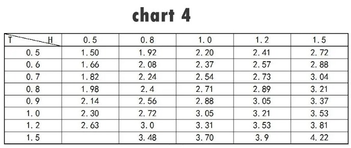
1. When the n-fold processing method is to fold and flatten the gasket, press
L = a + B + K. (see Table 4 for K value).
When n-fold is processed in other ways, it is calculated according to the general bending (R ≠ 0 θ≠ 90) “

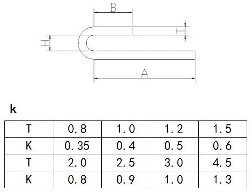
design value of dimension with tolerance:
take the middle value of upper and lower limit dimension as design standard value
Pre opening bottom hole
In the process of unfolding, in addition to the shape unfolding, we need to take out teeth (flanging) tapping, tapping (extruding and cutting) flanging expanding riveting nuts (class Z products), flower tooth pressing riveting nuts (class s products), pressing riveting screws (class FH products) and pressing riveting screws (class NY products) Rivet nut column (so, BSO, soo, SOPC products) (pay attention to the difference between 3.5m3 and M3 bottom hole). In the process of unfolding, the bottom hole should be pre opened (see Table 5 for details)
Open process hole
For some products with low precision and need to be welded and polished, we can open a bending process hole at the bending corner. The size is determined by the plate thickness. It should be larger than the plate thickness, and it should not be too large. In the programming process, we should try to select the appropriate mold that has been used. (easy to reduce mold and processing time).
No process hole is needed for all the edge lapping relationships;
There are three kinds of graphs: all inclusive, half inclusive and edge overlapping.
For the thickness t < 1.5mm, there is no need to open the process hole;
If the plate thickness t ≥ 1.5mm with edge wrapping, the process hole shall be added at the corner.
There are two kinds of process holes: round and U-shaped; the center of the long round hole is on the bending line.
As shown in figure A.B
The expanded part is the part of line segment, which is processed into the form of process hole as shown in the figure below: as shown in Figure C
The width of process hole is 0.5 (laser) or 2.0 (NCT).
when the distance between the Extraction edge and the bending edge (inner dimension) is less than 2.0 mm, the bending process will be affected. At this time, the corresponding bending deformation area will be cut or the extraction dimension will be changed, as shown in Figure E
Under the following circumstances, it is not allowed to open process holes:
Parts with appearance or assembly relationship requirements and without customer’s permission;
Separate shipment, without the customer’s permission.
Japanese customers didn’t ask to start yikong:
2) In the following cases, the programmer can open the process hole at his own discretion:
the workpiece that needs to be welded and filled up in the next process after opening the angle of the process hole;
the workpiece that is not the appearance surface and does not affect the assembly and function, and is assembled inside the whole machine for shipment.
In the following cases, the Engineer shall negotiate with the customer to open the process hole
Work pieces that affect bending or die forming but have no process holes on the drawing.
All the parts without fillet (laser) after product development shall be rounded according to r0.5.
what do we do about hole around a bending edge
It is worth noting that when we find that there is a hole close to the bending edge in the process of unfolding, and the hole will bend after bending, we need to inform the engineer whether to open the bottom hole first and then expand the hole after bending. ?
There are two general formulas for reference
LMIN=(2.0-2.5)T+D/2
L1 < V / 2 (V is V groove of lower die)
Smooth surface and burr surface
in the process of unfolding, smooth surface and burr surface are one of the important contents that we must consider. Generally, for those not specified in the drawing and not specially required by customers, such as folding a box, we usually regard the inside as burr surface and the outside as smooth surface. For customers (such as Japanese customers such as VGI, TBS, Seiko, etc.), there are special requirements, which are clearly indicated in the drawings. We will carry out according to the requirements of the drawings.
Requirements for unfolding in folding machine processing
The general form of bending process of folding machine is shown in the attached figure. The selection of V groove is related to the material thickness, and its minimum hem size is limited by V groove. Its relationship is shown in the attached table
Note: the minimum bending L in the table must be upper die with sharp knife;
The minimum h is Z-fold secondary molding (H ≥ 5T).
For Z-fold one-time forming (H ≤ 5T), the maximum length of Z-fold one-time forming is 835mm (2pcs), and there is no blocking in the middle.
The thickness of fault plate T: 0.5-2.3, the height of fault plate H: 0.5-10 mm.
Material saving placement: after the unfolding inspection is OK, we have to choose a reasonable placement method (generally x value > y value) to see how to place the most economical material, and rotate the unfolding drawing to a reasonable position (do not mirror, the burr surface will be reversed) And then arrange the knives.
