Jak pokazano na poni?szym rysunku, promień naro?a jest tworzony przez przeci?cie g?ównej kraw?dzi tn?cej i bocznej kraw?dzi tn?cej, zwanej równie? promieniem kraw?dzi.
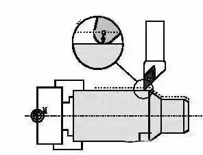
In the cutting process, in order to improve the tool tip strength and reduce the surface roughness of the machine, a circular arc transition edge usually exists at the tool nose. Besides, general non-reground blade has an arc as transition with certain radius. Even though as to exclusively sharpened turning tip, It still own a certain arched chamfer. There is no absolute corner on any turning tip.
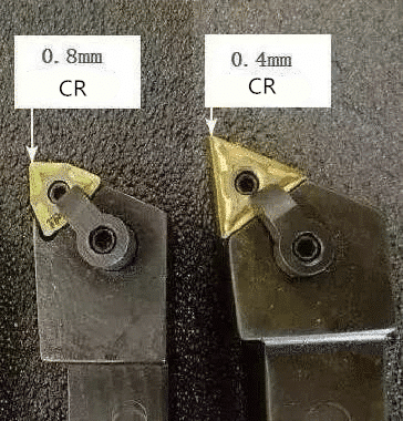
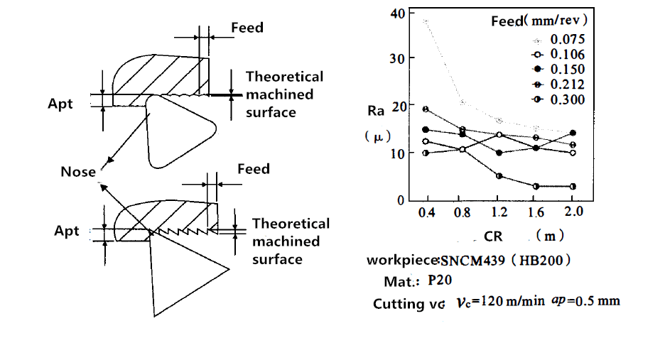
Through the comparison in Figure 1, it can be seen that the radius of the tool nose radius and the feed per rotation have the greatest impact on surface roughness of workpiece.To achieve the theoretical surface roughness requirements,the correct tool nose radius and feed rate must be selected. The figure below is a reference table of the relationship between values of these three elements. Generally, the corner radius of the tool tip is suitable for three to four times the feed rate.
| f | Ra | |||||
| r | 0.4 | 0.8 | 1.2 | 1.6 | 2.0 | |
| 1.6 | 0.07 | 0.1 | 0.12 | 0.14 | 0.16 | |
| 3.2 | 0.1 | 0.14 | 0.18 | 0.2 | 0.23 | |
| 6.3 | 0.14 | 0.2 | 0.25 | 0.28 | 0.32 | |
| 12.5 | 0.2 | 0.28 | 0.35 | 0.4 | 0.45 | |
| 25 | 0.28 | 0.4 | 0.49 | 0.56 | 0.63 |
r corner radius mm
f max feed per Rot. Mm
Ra Roughness μm
For the selection of the radius of the tool nose radius and the feed per rotation, it can also be determined by the theoretical empirical formula (1).
Ra=f2/r*125
Wherein:
Ra (μm) – surface roughness;
f(mm/rev) – feed per revolution;
r (mm) – the radius of the tool tip arc;
125 — constant.
Substituting the set value of the radius of the tool nose radius and the feed amount(1), we can calculate up the theoretical surface roughness and surface roughness as well.
E.g.: The radius of the tool nose arc is 0.8 mm, and the feed rate is
0.2 mm/r, substituting formula (1) for theoretical surface roughness.
Ra=0.22/0.8*125=6.25μm
The theoretical surface roughness is: 6.25 μm
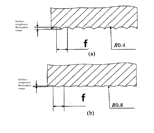
It is worth noting that if the radius is too large, vibration will occur due to excessive contact between the tool and the workpiece. Conversely, if the radius is too small, the tip will become weak and wear out quickly. Need to re-sharp often.Therefore, the fillet radius is generally 0.3~0.4mm.
Conner radius(edge radius) compensation
When machining CNC lathes, it is necessary to compensate for the corner radius.
When programming, the tool tip is usually considered as a point, but in practice there is a rounded corner. When the surface, such as the end face, the outer diameter, the inner diameter, and the like, which is parallel or perpendicular to the axis, is processed by a program programmed according to the theoretical tip point, no error occurs.
However, in the actual processing, there will be overcutting and multi-cutting. We will discuss the following two situations:
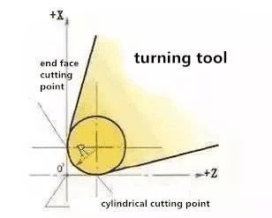
- Turning end face and inner and outer cylindrical faces
The figure below shows the tip of a circular arc and its orientation. The tool nose point used for programming and tool setting is the ideal tool tip point. Due to the presence of the tool nose arc, the actual cutting point is the tangent point of the tool edge arc and the cutting surface. When turning the end face, the actual cutting point of the tool nose arc is the same as the Z coordinate of the ideal tool tip point; when the outer and inner holes of the car are used, the X coordinate value of the actual cutting point and the ideal tool tip point are the same. Therefore, it is not necessary to perform the tool nose radius compensation when turning the end face and the inner and outer cylindrical faces.
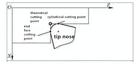
2) Turning the taper surface and the arc surface when machining taper surface and arc surface
When the machining path is not parallel to the machine axis, there is a positional deviation between the actual cutting point and the ideal tool tip point in the X and Z coordinate directions. The influence of the tool nose radius on the machining accuracy is shown in the figure below. If programmed with an ideal tool tip point, there will be less cut or overcutting, resulting in machining errors. The larger the radius of the tool nose arc, the greater the machining error.
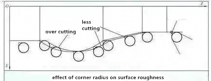
In the actual machining of the turning tool, due to the process or other requirements, the tool tip is often not an ideal point, but a circular arc. When machining cylindrical and end face contours parallel to the coordinate axis, the tool nose arc does not affect its size and shape, but when machining non-coordinate direction contours such as cones and arcs, the tool cutting point is at the tool edge arc. If it changes upwards, the arc of the tool tip will cause dimensional and shape errors, resulting in less or more cuts. This kind of machining error caused by the tooltip is not an ideal point but a circular arc, which can be eliminated by the tool nose radius compensation function.
