This paper aims to perform high-speed machining of TC4 titanium alloy using a vibration-damping end mill (end mill with unequal tooth pitch angles). The MATLAB software is used to perform a Fast Fourier Transform (FFT) on the milling force, with a focus on analyzing the impact of chatter on the machining of titanium alloys. The objective is to optimize the cutting speed while ensuring the quality of the machined surface and low cutting force, thereby improving cutting efficiency.
Dynamic Milling Force Model
To study the cutting stability, a reasonable dynamic model needs to be established. Compared to the workpiece with higher stiffness, the end mill can be considered as an elastic body. Since the end mill has a very high stiffness in the axial (z-direction) direction, the milling machining system can be simplified into a “spring-damping” system with two mutually perpendicular degrees of freedom in the x-direction (feed) and y-direction, as shown in Figure 1. Φj(t) represents the rotation angle of the end mill; hi(t) represents the dynamic chip thickness; fz is the feed per tooth.
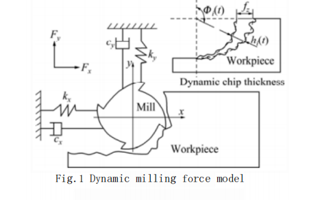
Establishing the equations of motion for 2 degrees of freedom?movement:

In the formula: m, s, c, k represent the mass, displacement, damping coefficient, and elastic coefficient of the cutting system, respectively; Fx(t) and Fy(t) are the dynamic milling forces in the x and y directions, respectively. The milling forces studied in this paper are all Fy, and the motion equation is simplified to a single degree of freedom motion equation:
![]()
The milling force Fy(t) is related to the dynamic chip thickness hi(t) during the milling process and is a function of the end mill’s rotation angle φj(t), making it a periodic function. The variation frequency of the cutting force is the tool tooth passing frequency (TPF). Due to manufacturing and clamping errors causing the tool system to be asymmetric, its variation frequency is the spindle rotation frequency (SF).
The spindle rotation frequency (SF) is defined as:
![]()
In the formula: ω is the angular velocity of the spindle rotation, in radians per minute; v is the linear velocity of the spindle, in meters per minute; D is the diameter of the end mill, in millimeters; the unit of spindle rotation frequency is Hz.
The tool tooth passing frequency (TPF) is defined as:

In the formula: N represents the number of teeth on the end mill.
Milling Experiment
Experimental Setup, Workpiece Material, and ??? ??
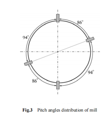
The milling experiment setup is shown in Figure 2. The machine used is a DAEWOO ACE-V500 machining center with a rated power of 15 kW and a maximum torque of 286.2 N?m. The milling force is measured by a Kistler 9257B three-coordinate force measuring instrument with a sampling frequency of 7,000 Hz. The cutting tool used is a 4-fluted variable pitch solid carbide end mill, and the distribution of the tooth pitch angles at the bottom is shown in Figure 3. The diameter of the end mill is 20 mm, and the overhang length is 74.3 mm. The workpiece material is TC4 titanium alloy.

Section 2.2: Experimental Design
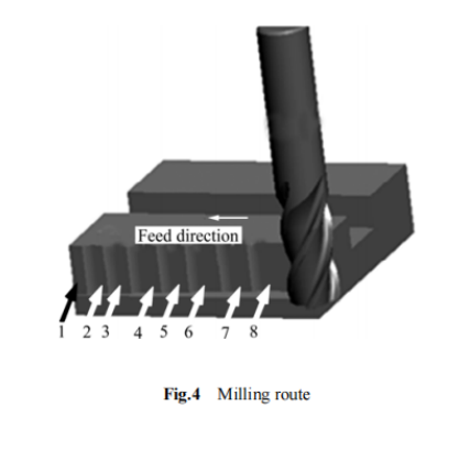
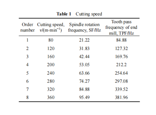
The experiment was conducted using dry cutting and conventional milling. The cutting speed v, spindle rotation frequency (SF), and tool tooth passing frequency (TPF) are listed in Table 1. The feed per tooth fz, axial cutting depth ap, and radial cutting depth ae were kept constant at 0.08 mm/tooth, 20 mm, and 0.5 mm, respectively. The range of cutting speed varied from 80 to 360 m/min. Figure 4 shows the milling sequence, where the sequence numbers correspond to those in Table 1.
Experimental Results
Time-Domain Analysis of Cutting Forces
Figure 5 shows the relationship between the maximum amplitude of Fy and the cutting speed (v). From the figure, it can be observed that when the cutting speed is in the range of 80~160 m/min, the maximum milling force remains essentially unchanged. When the cutting speed reaches 200 m/min, the milling force suddenly increases, and when the cutting speed reaches 240 m/min, the milling force reaches its first peak. Subsequently, as the cutting speed increases,The cutting force significantly decreases until the cutting speed increases to 320 m/min, at which point the milling force reaches its minimum. When the cutting speed is 360 m/min, the milling force reaches its maximum value.

Analysis of Milling Force Spectrum
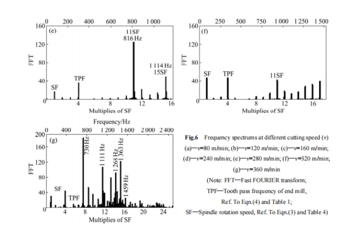
The frequency domain provides more information about the cutting process than the time domain. As the direct responder of the tool and workpiece, the milling force can describe the vibration condition of the cutting system. From the collected y-direction milling force Fy signal, a 4-second segment of data in the middle was selected and processed using MATLAB software for Fast Fourier Transform (FFT) to analyze the milling force spectrum and determine the machining condition.
Since the variation frequency of the milling force is TPF, the peaks of the milling force generally appear at TPF and its integer multiples (n·TPF) in the frequency domain. However, due to tool manufacturing and mounting errors, the variation frequency of the milling force is often SF, meaning the spectrum peaks of the milling force appear at SF and its integer multiples (n·SF).
Figures 6(a) to (h) show the milling force spectrum analysis at different cutting speeds. From the figures, it can be seen that when the cutting speed is 80 and 120 m/min, the peaks of the milling force spectrum appear at the spindle rotation frequency (SF) and the tool tooth passing frequency (TPF). When the cutting speed is 160, 280, and 320 m/min, the peaks of the milling force appear not only at SF and TPF but also at high frequencies. The peak at the spindle rotation frequency (SF) is larger at higher cutting speeds than at lower cutting speeds, which is due to the mass imbalance caused by tool eccentricity. As the cutting speed increases, the centrifugal force increases, leading to an increase in the y-direction milling force peak. When the cutting speed is 240 and 360 m/min, the larger peaks at high frequencies do not appear at SF and its integer multiple frequencies, indicating that chatter occurs in the cutting system at these times, with chatter frequencies of 734 Hz (v=240 m/min), 730 Hz, 1,111 Hz, 1,268 Hz, 1,363 Hz, and 1,459 Hz (v=360 m/min). Combined with Figure 5, it can be determined that when chatter occurs, the radial milling force increases significantly.
Machined Surface Quality
The Wyko NT9300 white light interferometer was used to measure the machined surface topography. This instrument uses the principle of optical interference and can achieve nanometer precision in topography measurement.
Figure 7 shows the machined surface topography measured by the white light interferometer. From the figure, it can be seen that when v=160 m/min, the surface topography is the best. When v=240 and 360 m/min, there is a large area of material removal on the machined surface. This is partly due to chatter, which increases friction, extrusion, and tearing between the tool and the workpiece, causing the tool to produce unstable vibrations on the workpiece surface, leading to overcutting in some areas. On the other hand, these violent movements cause the cutting temperature to rise, resulting in adhesion between the flank of the tool and the workpiece. As the tool moves, most of the adhered workpiece material is carried away by the tool.

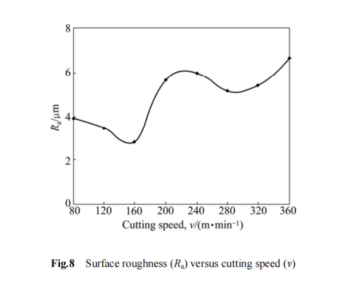
By comparing Figure 5 with Figure 8, it is found that the roughness curve follows a similar trend to the cutting force curve. When chatter occurs (at cutting speeds of 240 and 360 m/min), both the cutting force and roughness reach their maximum values, proving that chatter not only increases the cutting force but also increases the surface roughness.
From Figure 8, it can also be seen that for stable cutting (cutting speeds of 80 to 160 m/min), the higher the cutting speed, the lower the surface roughness. Although stable cutting occurs at cutting speeds of 200 and 280 m/min, Figures 6(d) and (f) show that the high-frequency peaks of the milling force are significant, which affects the surface quality. When the cutting speed is 320 m/min, the cutting force is small, and the spectrum peaks are also small, but the surface roughness is poor. This is due to the tool eccentricity (larger peak at SF) having a significant impact on surface roughness at high cutting speeds.
??
Under dry cutting conditions, when high-speed milling TC4 titanium alloy, chatter occurs at cutting speeds of 240 m/min and 360 m/min, with chatter frequencies around 730, 1,111, 1,363, and 1,459 Hz.
For stable cutting, the cutting speed has little effect on the magnitude of the milling force. However, when chatter occurs, the cutting force significantly increases, and the surface quality of the machining deteriorates.
At a cutting speed of 160 m/min, the surface roughness is low, and the cutting force is small, so 160 m/min can be recommended as the optimal cutting speed.


