The structural shape of a part shall not only meet the design performance requirements, but also meet the processing process requirements. Therefore, it is necessary to understand the common process structure on parts.
Process structure of casting parts (including drawing of transition line)
The process structure of casting parts includes mold inclination, casting fillet, casting wall thickness, etc.
1. Formwork lifting slope
When casting parts, in order to facilitate mold taking, a certain slope is often designed along the mold starting direction on the casting wall, that is, the mold starting slope. For the structure with small inclination, it may not be drawn on the graph, but the value of mold lifting inclination must be explained in words in the technical requirements. As shown in Figure 1.
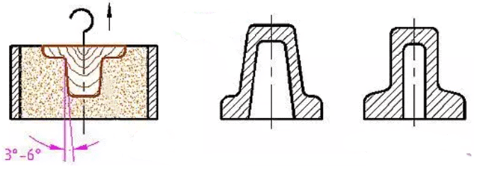
Figure 1
2. Cast fillet
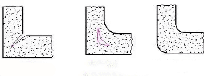
When casting parts, in order to prevent sand falling from the casting sand mold and avoid cracks or shrinkage cavities during casting cooling (as shown in Fig. 2), the intersection of casting surfaces shall be made into fillet transition, as shown in Fig. 3. Generally, the cast fillet shall be drawn in the drawing. When the radius of each fillet is the same or close, the radius value can be uniformly noted in the technical requirements, such as cast fillet R3 ~ R5, etc.
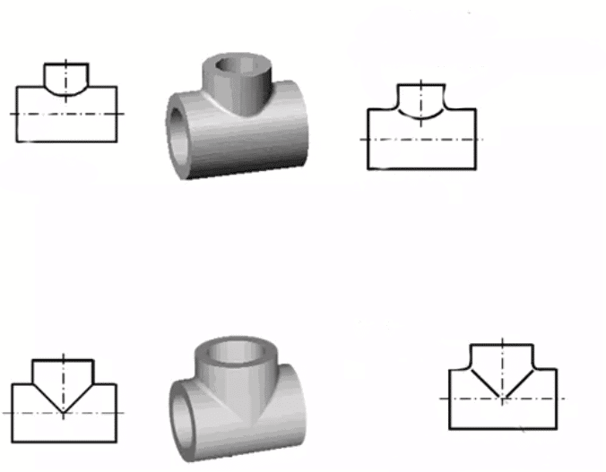
Because there are casting fillets at the intersection of casting surfaces, the intersection line of two surfaces becomes less obvious. However, on the part drawing, the theoretical intersection line of the surface must still be drawn, but it is required to leave a blank at both ends or one end of the intersection line, which is usually called the transition line. The drawing method of transition line is basically the same as that of intersection line without fillet. The differences between them are shown in Figure 4.
3. Casting wall thickness
In order to avoid cracks or shrinkage cavities caused by internal stress during casting cooling, the wall thickness of the casting shall be as uniform as possible, and the transition between different wall thicknesses shall also be uniform, as shown in Figure 5.
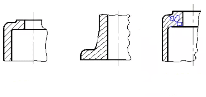
Figure.5
Cutting process structure of metal parts
The cutting process structure of metal parts includes chamfering and rounding, tool return groove or grinding wheel over travel groove, reasonable structure of drilling, boss and pit, etc.
1. Chamfering and rounding
In order to facilitate assembly, chamfer is often machined at the shaft end or orifice, as shown in Fig. 6 (a). In order to avoid cracks on the stepped shaft or hole due to stress concentration, fillets are often machined at the turning point of the shoulder, as shown in Fig. 6 (b). The type and size of chamfering and rounding of parts shall be specified in the national standard.
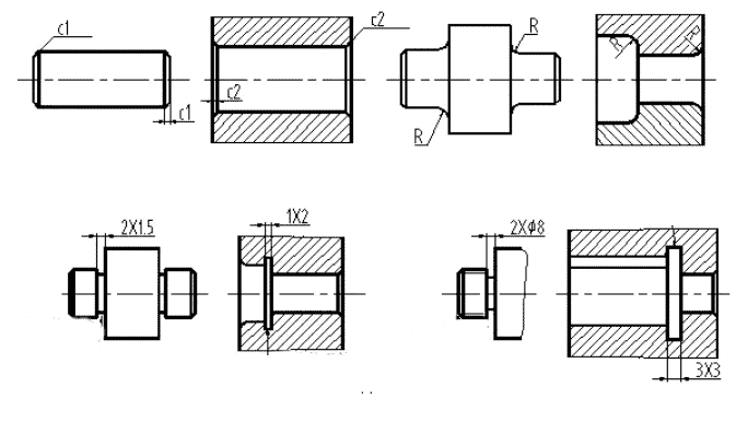
Figure.6
2. Undercut or grinding wheel over travel groove
In order to easily withdraw the tool during cutting and ensure the machining quality, the tool withdrawal groove or grinding wheel over travel groove is often machined at the shoulder of the machining surface, as shown in Fig. 6 (c). The structure and size of the over travel groove of the grinding wheel are specified in the national standard.
3. Bosses or pits
In order to reduce the amount of machining and ensure good indirect contact of parts during assembly, bosses or pits are often made on the surface of parts.
4. Reasonable drilling structure
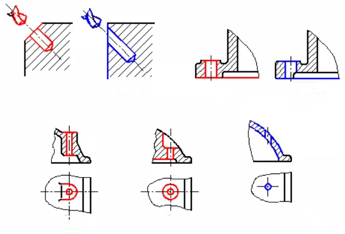
In order to avoid axis deflection and bit breaking during drilling, the axis of the hole shall be perpendicular to the end face of the hole. Therefore, when there is a drilling structure on the inclined surface, a plane, boss or pit perpendicular to the drilling direction shall be designed, as shown in Figure 8.
Cutting process structure of metal parts
The cutting process structure of metal parts includes chamfering and rounding, tool return groove or grinding wheel over travel groove, reasonable structure of drilling, boss and pit, etc.
1. Chamfering and rounding
In order to facilitate assembly, chamfer is often machined at the shaft end or orifice, as shown in Fig. 6 (a). In order to avoid cracks on the stepped shaft or hole due to stress concentration, fillets are often machined at the turning point of the shoulder, as shown in Fig. 6 (b). The type and size of chamfering and rounding of parts shall be specified in the national standard.
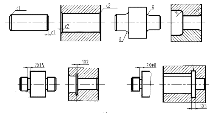
Figure.6
2. Undercut or grinding wheel over travel groove
In order to easily withdraw the tool during cutting and ensure the machining quality, the tool withdrawal groove or grinding wheel over travel groove is often machined at the shoulder of the machining surface, as shown in Fig. 6 (c). The structure and size of the over travel groove of the grinding wheel are specified in the national standard.
3. Bosses or pits
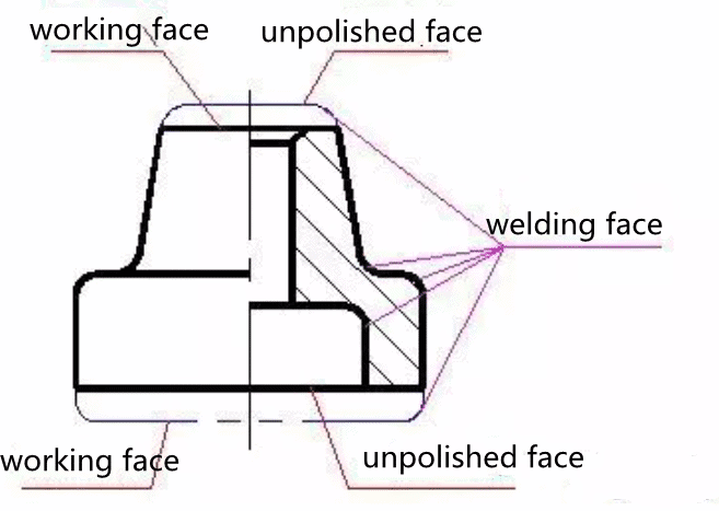
In order to reduce the amount of machining and ensure good indirect contact of parts during assembly, bosses or pits are often made on the surface of parts, as shown in Figure 7
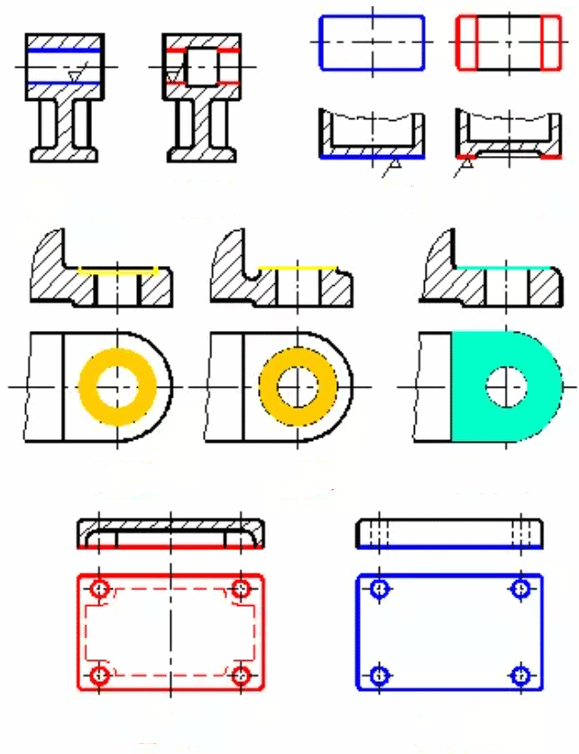
Figure.7
4. Reasonable drilling structure
In order to avoid axis deflection and bit breaking during drilling, the axis of the hole shall be perpendicular to the end face of the hole. Therefore, when there is a drilling structure on the inclined surface, a plane, boss or pit perpendicular to the drilling direction shall be designed, as shown in Figure 8.
