Process Measures to Reduce Machining Deformation
Reducing Residual Stress in Blanks
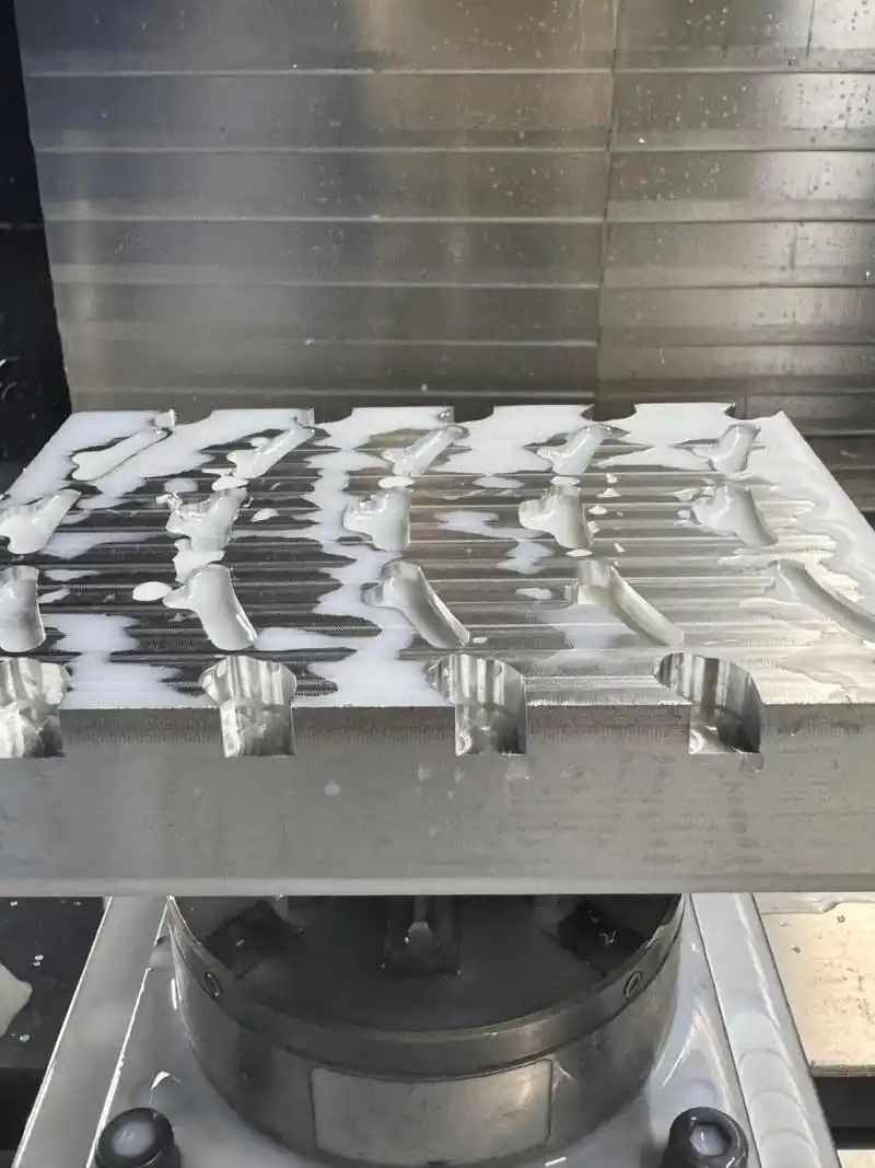
Natural or artificial aging, as well as vibration treatment, can partially eliminate residual stresses in blanks. Pre-machining is also an effective method. For bulky blanks with excessive stock allowance, post-machining deformation tends to be significant. By pre-machining to remove excess material and balance stock allowance, subsequent machining deformation can be reduced. Additionally, allowing the pre-machined blank to rest helps release residual stresses.
Improving Tool Cutting Performance
Tool material and geometric parameters significantly influence cutting forces and heat generation. Proper tool selection is crucial for minimizing part deformation.
Optimizing Tool Geometry
Rake Angle:
A larger rake angle (while maintaining edge strength) enhances cutting sharpness, reduces chip deformation, improves chip evacuation, and lowers cutting forces and temperatures. Negative rake angles should be avoided.
Clearance Angle:
The clearance angle directly affects flank wear and surface finish. For rough milling with heavy loads and high heat, a smaller clearance angle improves heat dissipation. For finish milling, a larger clearance angle reduces friction and elastic deformation.
Helix Angle:
A higher helix angle ensures smoother milling and reduces cutting resistance.
Lead Angle:
A smaller lead angle improves heat dissipation and lowers average cutting zone temperatures.
Enhancing Tool Structure
Reducing Teeth Count & Increasing Chip Space:
Aluminum’s high plasticity demands larger chip pockets. Tools with fewer teeth and wider gullets are preferred.
Precision Edge Honing:
The cutting edge roughness should be below Ra = 0.4 μm. Lightly honing new tools with a fine stone removes burrs and micro-serrations, reducing heat and deformation.
Strict Wear Control:
Tool wear increases surface roughness, cutting temperature, and part deformation. Wear limits should not exceed 0.2 mm to prevent built-up edge. Workpiece temperature should stay below 100°C to avoid distortion.
Optimizing Workpiece Fixturing
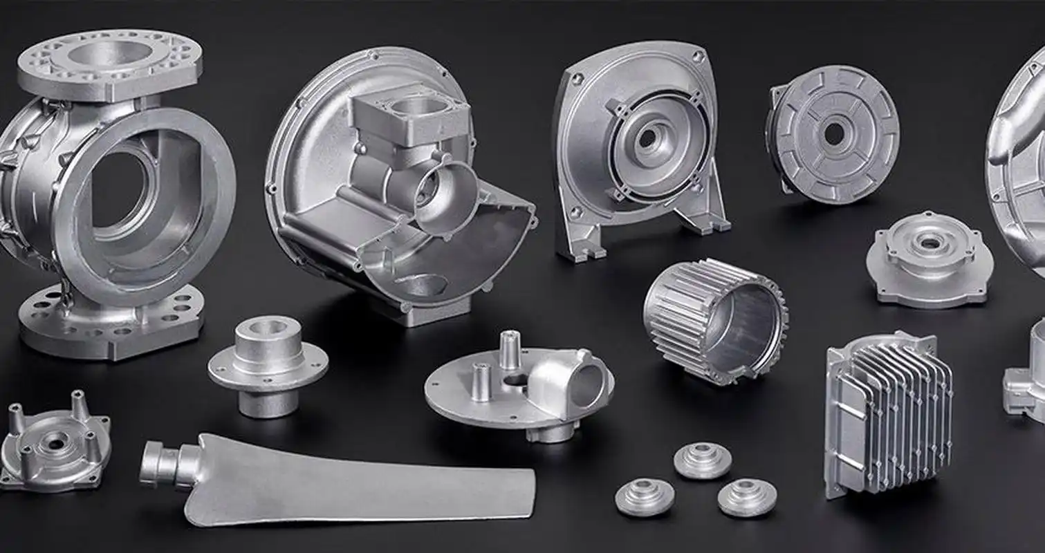
For thin-walled aluminum parts with low rigidity:
Axial Clamping for Bushings
Radial clamping (e.g., 3-jaw chucks) causes post-machining deformation. Instead, use a threaded mandrel inserted into the part’s bore, secured axially with a endplate and nut to maintain precision during OD machining.
Vacuum Chucks for Thin Plates
Uniform clamping force distribution paired with light cuts minimizes distortion.
Filling Method
Fill hollow parts with a low-melting filler (e.g., urea-potassium nitrate melt) to enhance rigidity during machining. Dissolve the filler post-process in water/alcohol.
Strategic Process Sequencing
High-speed machining with large stock or interrupted cuts may induce vibration. A typical CNC process flow:
Roughing → Semi-finishing → Corner Cleaning → Finishing
For high-precision parts, repeat semi-finishing before final passes. Post-roughing natural cooling relieves stresses. Leave 1–2 mm stock after roughing; maintain 0.2–0.5 mm uniform allowance in finishing to ensure stability, reduce deformation, and achieve high surface quality.
Operational Techniques to Minimize Machining Deformation
In addition to the aforementioned causes, operational methods play a crucial role in controlling deformation during aluminum part machining.
Symmetrical Machining for Large Stock Parts
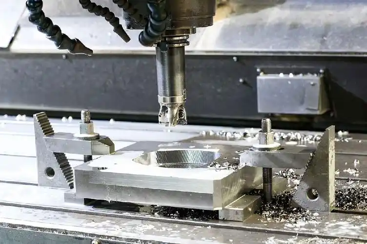
For better heat dissipation, use alternating symmetrical machining. Example: A 90mm plate machined to 60mm achieves 0.3mm flatness when processed in alternating passes versus 5mm with consecutive machining.
Layered Machining for Multi-cavity Parts
Machine all cavities layer-by-layer simultaneously to ensure uniform stress distribution, preventing deformation from uneven forces.
Optimized Cutting Parameters
Adjust depth of cut (ap) with corresponding feed rate and spindle speed increases in CNC high-speed milling to balance productivity and reduced cutting forces.
Strategic Tool Path Selection
Use conventional milling for roughing (maximum removal rate) and climb milling for finishing (better surface quality with progressive chip thickness reduction).
Thin-wall Fixturing Technique
Before final passes, briefly release and reapply minimal clamping force to allow natural recovery, applying force along the part’s most rigid direction.
Cavity Machining Method
Avoid direct plunging; pre-drill or use helical entry paths to prevent chip packing and tool breakage.
Conclusione
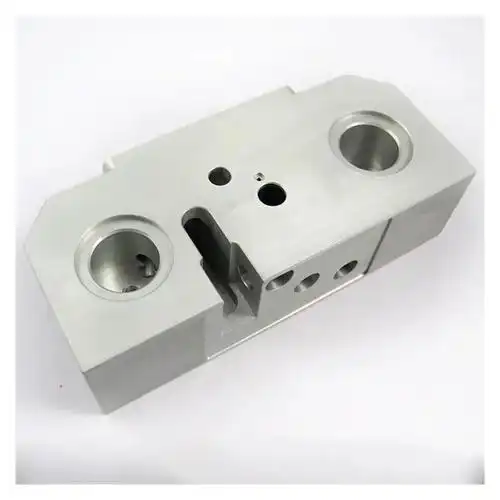
Aluminum part deformation stems from material properties, geometry, and processing conditions, primarily involving?blank residual stresses,cutting forces/heat,and clamping stresses.The integrated application of these process optimizations and operational techniques significantly reduces deformation, enhances precision and surface quality, providing reliable technical support for production.
]]>They can be usefully used for finishing stands of high-speed wire rod mills (up to 120 m/s),precision rotolamento of rebars, alloy steels, and non-ferrous metals, and high-reduction passes where wear resistance is critical
Practical condition
Located in Guangdong Province, A metal production company commissioned its high-speed wire rod mill (with an annual capacity of 1.2 million tons of φ5.5~φ16mm wire rods) in December 2010 to enhance production efficiency and meet market demands.
The mill primarily consists of five key components: roughing mill, intermediate mill, pre-finishing mill, and finishing mill. The roughing mill features a single-line configuration with 5 stands (φ550×5) arranged in horizontal-horizontal-vertical-horizontal-vertical (HHVHV) pattern. The intermediate mill comprises 8 stands (φ550×2+φ450×4+φ350×2) with all-horizontal rolls. The pre-finishing mill has 8 stands (dual-line, 4 stands per line) configured as cantilever-type two-high mills (φ285×4×2) with alternating horizontal/vertical arrangement. The finishing mill contains 20 stands (dual-line, 10 stands per line) of cantilever-type two-high mills (gang-driven, φ228×5+φ170×5) in 45° top-cross configuration.
Due to humid climatic conditions, the mill encountered roll ring explosions caused by moisture-induced rusting of roll rings and taper sleeves. A technical task force was established to identify root causes and implement corrective measures to ensure stable production.

Production Process Overview
The manufacturing process flows as follows:
1.After single-pass rolling in the roughing mill, the billet undergoes head/tail cropping at #1 flying shear (with emergency scrap chopping capability), then diverges into dual lines via a distributor for intermediate rolling under micro-tension control.
2.Following intermediate rotolamento, the stock passes through #2 flying shear for cropping before entering pre-finishing mill, where pneumatic vertical loopers enable twist-free, tensionless rolling for precise dimensional control.
3.Pre-finished stock undergoes water cooling and #3 flying shear cropping before entering finishing mill. Emergency shutoff shears activate to prevent further stock entry during malfunctions.
4.The 45° top-cross finishing mill employs gang-driven tungsten carbide roll rings for twist-free micro-tension rolling, achieving final dimensions at speeds up to 95m/s for φ5.5~7mm products.

Root Cause Analysis of Roll Ring Failures
The cost-optimized tungsten carbide roll rings exhibited these failure mechanisms:
Ambient humidity caused rust corrosion at roll ring/taper sleeve interfaces
Thermal fatigue from cyclic temperature variations (Fig.1) accelerated crack propagation
Insufficient cooling exacerbated thermal stresses (increased ΔT)
Improper assembly caused taper sleeve seizure
Brittle material properties increased handling damage risks
Technical Improvements & Process Controls
Material Selection Optimization
The YGR-series roll rings were selected for their Ni/Cr-enhanced properties:
1.Superior oxidation resistance (700-1000℃)
2.Improved acid corrosion resistance (pH≤7.2)
3.Enhanced thermal crack resistance
4.Optimal hardness-toughness balance across mill stands
Cooling System Enhancements
Implemented strict water management protocols:
1.Flow rates: 18-25m3/h per stand (slot-width dependent)
2.Pressure maintenance: 3-7bar at nozzles
3.Monthly water quality testing for particulate control
Dedicated pipe alignment inspections during maintenance
Optimum Rolling Tonnage
Established safe grinding thresholds at 0.2-0.4mm crack depth:
Stands 1-4: 1,800-2,500 tons
Stands 5-8: 1,500-2,000 tons
Stands 9-10: 600-1,000 tons
Precision Assembly Standards
Mandatory surface cleaning before assembly
Prohibited impact mounting methods
Individual roll storage in partitioned containers
Strict taper sleeve inspection/rejection criteria
Conclusione
The comprehensive improvement program addressing material selection, cooling optimization, production control, and precision maintenance successfully resolved roll ring failures, achieving sustained operational stability. This methodology provides valuable reference for similar applications.
Key Recommendations
1.Select roll ring grades considering environmental factors
2.Maintain rigorous cooling water quality standards
3.Adhere to prescribed rolling tonnage limits
4.Implement precision handling and maintenance protocols
]]>Basic Definitions of Positive and Negative Rake Angle Tools
Positive Rake Angle Tool
A positive rake angle tool refers to a turning tool where the front face is inclined toward the interior of the workpiece relative to the cutting point, resulting in a positive rake angle (typically +5° to +15°). Its structural characteristic is a relatively sharp cutting edge, with a smaller contact area between the front face and the chip.
Negative Rake Angle Tool
A negative rake angle tool, on the other hand, has a front face inclined outward from the workpiece relative to the cutting point, resulting in a negative rake angle (typically -5° to -10°). Its structural feature is a blunter cutting edge, with a thicker and more robust tooltip.
Advantages and Disadvantages of Positive and Negative Rake Tools
Positive Rake Angle Tool
Advantages:
Lower Cutting Forces: A positive rake angle allows smoother chip flow and reduces deformation, decreasing main cutting forces by 15–25%.
Better Chip Evacuation: Shorter chip-tool contact length reduces built-up edge formation.
Suitable for Finishing: Minimizes vibration, enabling better surface finish (Ra < 1.6 μm).
Svantaggi:
Lower Tooltip Strength: The positive geometry reduces material support, making the tool prone to chipping in interrupted cuts or hard materials.
Poor Heat Dissipation: Smaller chip-tool contact area limits heat transfer, accelerating crater wear at high speeds.
Shorter Tool Life: Typically 60–70% of negative rake tools under the same conditions.
Negative Rake Angle Tool
Advantages:
High Tooltip Strength: The negative angle creates a “support wedge,” improving impact resistance by >50%.
Superior Heat Dissipation: Larger chip-tool contact area enhances heat conduction, reducing cutting temperatures by 15–30°C.
Multi-Sided Usability: Often designed with double-negative angles, allowing flipping for extended use.
Limitations:
Higher Cutting Forces: Negative rake increases chip deformation, raising main cutting forces by 20–30%.
Greater Power Demand: Requires 15–20% more motor power from the machine tool.
Vibration Risk: Prone to chatter in long overhang machining due to increased cutting forces.
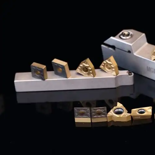
Experimental Comparison
The following systematic experiment compares the performance of carbide positive and negative rake tools under different machining conditions, providing practical insights for tool selection.
Experimental Design
1.Materials & Equipment:
Positive rake tool (+8° rake angle)
Negative rake tool (-6° rake angle)
Both use YG8 carbide substrate with TiAlN coating and 0.4 mm nose radius.
2.Workpiece:45# steel (Φ50×200 mm), quenched and tempered to HRC 28–32.
3.Machine:CA6140 lathe with 3-jaw chuck and tailstock center.
4.Measurement Instruments:
Surface roughness tester (Mitutoyo SJ-210)
Electron microscope (OLYMPUS DSX510)
Cutting force dynamometer (Kistler 9257B)
Infrared thermometer (Fluke Ti400)
5.Parameters
Fixed: Depth of cut (ap = 1 mm), feed rate (f = 0.15 mm/rev).
Variable: Cutting speed (v = 60–180 m/min).
Three repetitions per condition for reliability.
Results & Analysis
Tool Wear & Life Comparison
Using flank wear VB = 0.3 mm as the failure criterion:

Negative rake angle tools demonstrate significantly longer service life, exceeding positive rake tools by an average of 50-70%. Analysis of wear patterns reveals that positive rake tools primarily fail through crater wear on the rake face and tooltip chipping, whereas negative rake tools exhibit more uniform flank wear, demonstrating superior fracture resistance.
Cutting Force Comparison

The data shows that under all tested cutting speeds, negative rake tools generate significantly higher principal cutting forces than positive rake tools, with an average increase of approximately 17%. This is attributed to the negative rake design’s larger contact area between the tool’s rake face and chips, as well as intensified cutting deformation. Notably, while cutting forces for both tool types decrease with increasing cutting speed, the difference ratio remains essentially stable.
Cutting Temperature Comparison
Results indicate that negative rake tools maintain consistently lower cutting temperatures than positive rake tools, typically by 15-25°C. This thermal advantage primarily stems from the negative rake design’s enhanced tooltip strength and improved heat dissipation capacity. The temperature difference becomes particularly pronounced during high-speed cutting (v>120m/min), reaching approximately 30°C.
Surface Quality Evaluation
Surface roughness serves as a critical indicator of machining quality. At a feed rate of f=0.15mm/rev, measurements show:
Positive rake tool surface roughness (Ra): 1.6-2.0μm
Negative rake tool surface roughness (Ra): 1.2-1.5μm
Electron microscope observations reveal that surfaces machined with negative rake tools exhibit more uniform texture patterns with fewer burrs and vibration marks. This improvement results from the negative rake design’s enhanced system rigidity that reduces cutting vibrations. Furthermore, negative rake tools maintain more stable tooltip geometry during machining, avoiding the surface quality degradation caused by micro-chipping that often occurs with positive rake tools.
Conclusions
1.While carbide negative rake tools show slightly inferior performance in cutting force, they demonstrate clear advantages in cutting temperature control, surface quality, and tool life.
2.The performance advantages of negative rake tools become more pronounced at higher cutting speeds, making them particularly suitable for modern high-speed machining requirements.
3.Positive rake tools excel in reducing cutting forces and are better suited for machining systems with limited rigidity.
4.Optimal tool angle selection should comprehensively consider multiple factors including workpiece material, machine tool conditions, and specific machining stages.
]]>
Physical Nature of Coating Thickness and Functional Realization
The physical essence of coating technology lies in modifying interfacial properties of the substrate via surface engineering. For rotating tools like drills, coatings must simultaneously reduce friction, enhance surface hardness, and inhibit thermal conduction. When coating thickness ranges from nanometers to micrometers, significant size effects emerge in mechanical properties. Experimental data shows that TiN coatings reach peak microhardness (≈2300HV) at 2-3μm thickness; further increases reduce hardness due to accumulated residual stress. This stress heterogeneity creates preferential paths for microcrack propagation during drilling, especially under interrupted cutting conditions, where excessively thick coatings are prone to delamination.
Thermal barrier effects are vital, but thermal conductivity does not scale linearly with thickness. Finite element simulations reveal that beyond 5μm, AlCrN coatings show diminishing thermal resistance gains. Excessive thickness may impede heat dissipation, intensifying thermal stress concentration in high-speed machining.
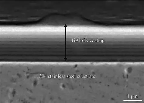
Dynamic Evolution of Cutting Edge Geometry
Drill edge sharpness directly affects chip evacuation and force distribution. The “rounding effect” during deposition causes exponential growth in edge radius with thickness. For DLC coatings increasing from 1μm to 3μm, edge radius swells from 3.2μm to 8.7μm, raising cutting resistance by 23%. This geometric dulling is pronounced in ductile materials—aluminum alloy tests show a 15% rise in chip buildup probability per micrometer increase in edge radius. Paradoxically, moderate dulling suppresses edge chipping in brittle materials, highlighting the need for material-specific thickness optimization.
Coating thickness impacts flute hydrodynamics, often overlooked. 3D flow simulations show that when coating exceeds 12% of flute depth, secondary chip flow intensifies, causing blockages. In deep-hole drilling, this exacerbates radial vibration, increasing borehole deviation. A German toolmaker reduced straightness errors by 40% by decreasing TiAlSiN thickness from 4μm to 2.5μm.
Multiscale Correlation of Interface Failure Mechanisms
Coating-substrate bond strength does not monotonically change with thickness. Interface energy tests reveal a 30% strength drop when CrN exceeds ~4μm, due to lattice mismatch stress accumulation. This weakening is perilous under cyclic loading, with failures originating at nanoscale voids. Gradient transition layers enhance critical thickness—inserting a 50nm Ti interlayer between WC-Co and TiCN boosts critical thickness from 3.2μm to 5.1μm.
Cyclic loading reveals time-dependent failure. Accelerated life tests show 3μm AlTiN coatings reduce crack growth by 67% after 10? impacts, benefiting from crack closure effects. Beyond 2×10? cycles, thicker coatings exhibit larger spalling areas, indicating an optimal thickness for fatigue life. This non-monotonic relationship demands precise service life predictions.
Implicit Links to Machining Precision and Surface Integrity
Coating thickness has dual impacts on precision. In micro-hole drilling, a 2μm thickness deviation causes 0.8-1.2% diameter variation. A Japanese firm’s adaptive coating technology deposits 1.5μm at the tip and 2.2μm at margins, controlling diameter?floating?to 0.3%. Such differential designs surpass conventional uniform coatings.
Residual stress in workpieces couples with coating thickness. XRD analysis shows a drop from -450MPa to -280MPa when thickness increases from 1μm to 3μm, potentially reducing dimensional stability. However, thicker coatings reduce heat-affected zones by 35%, critical for aerospace aluminum.
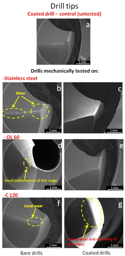
Economic Considerations and Technological Trends
Coating cost scales with thickness squared, but lifespan gains have inflection points. An automotive plant found that increasing TiAlN from 2μm to 3μm raised costs by 18% while only improving life by 12%, resulting in negative ROI. However, nano-multilayered 2.5μm coatings outperformed 3μm by 25%, indicating that thickness alone is suboptimal.
Future coatings will feature intelligent thickness control. Digital twin-based optimization systems are operational, adjusting parameters via real-time force/temperature feedback. A German AI system predicts optimal thickness in 48 hours, enhancing performance by >30%. Dynamic adaptation may revolutionize traditional thickness determination.
Conclusione
Coating thickness orchestrates a precision symphony in drill performance, where each parameter adjustment triggers cascading effects. Modern engineers must transcend empirical selection, establishing multi-physics digital design paradigms. Future breakthroughs may lie in self-sensing smart coatings with dynamic thickness adjustment, potentially sparking a new revolution. In this era of precision and intelligence, mastering coating thickness will benchmark a nation’s advanced manufacturing prowess.
]]>
Contamination
Characteristics: Contamination is characterized by the presence of unevenly sized pores inside the cemented carbide product, with corresponding surface protrusions or holes.
If the surface is slightly contaminated and can be machined without leaving holes, the product can be considered qualified and released.
If the surface is severely contaminated or exhibits blistering, it should be classified as scrap.
Causes of Contamination
During the high-temperature sintering stage, gases generated by internal reactions in the sintered body escape or migrate to the surface. By this time, the liquid phase has already begun to solidify, leaving behind small pores that cannot recover in time, and the gases migrating to the surface are not completely expelled.
Certain difficult-to-reduce oxides are only reduced at the temperature where the liquid phase forms. The pressure of the gases produced by reduction exceeds the resistance of the liquid phase contraction, leading to blister formation.
1.Excessive temperature (over-sintering) causes a significant increase and aggregation of the liquid phase, resulting in blistering.
2.Impurities in the pressed blocks, such as carbide chips or copper wires, can also cause blistering (contamination).
3.Severe delamination in the pressed product can also manifest as blistering during sintering.
Sources of Contamination
1.Oxidized block materials, oxidized granular materials, and defective pressed blanks.
2.Metal impurities: Screen mesh debris, cobalt chips.
3.Non-metal impurities: Ceramic fragments, glass fragments, boat-filling materials, dust, brush debris, etc.
4.Forming agents: Unremoved mechanical impurities, unfiltered gel, uneven forming agents, aged forming agents, etc.
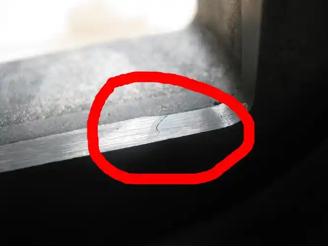
Deformation
Characteristics: The geometric shape of the carbide product undergoes irregular changes, and warped products exhibit a regular curved deformation on a specific plane.
For such deformedcarbide products, inspections should be conducted according to standards or product drawings. Products that exceed tolerance limits should be returned to the production unit for reprocessing, and those that cannot be reprocessed should be classified as scrap.
Causes of Deformation Defects
1.Uneven density of the pressed product: This leads to uneven shrinkage during sintering. Areas with higher density shrink less, while areas with lower density shrink more.
2.Uneven carbon atmosphere around the pressed blank: This causes deformation of the product.
3.Uneven temperature environment during sintering: The pressed blank deforms due to temperature inconsistencies in the sintering environment.
4.Other reasons: Improper loading of the sintering boat, uneven placement of the base plate, etc.

Peeling
Characteristics: Peeling is characterized by the appearance of irregular branch-like cracks, cracks, or flaking at the edges and corners of the alloy product. In mild cases, it presents as a network of cracks, while in severe cases, small pieces may peel off. In extreme cases, the product may crack and peel off entirely, with cotton-like carbon black deposits clearly visible at the peeling sites. Carbide products with peeling are directly classified as scrap.
Causes of Peeling
1.High concentration of carbon-containing gases in the low-temperature zone: High concentrations of carbon-containing gases penetrate weak areas of the product (such as edges and corners, which often have lower density or significant elastic aftereffects). Under the catalytic action of cobalt, carbon precipitation reactions occur:
CH=C+H 2
CO =?C+CO
The precipitated carbon disrupts the continuity of the carbide, leading to peeling. In other words, the decomposition of carbon-containing atmospheres into large amounts of free carbon is the primary cause of peeling.
2.Vacuum dewaxing stage: If the dewaxing temperature exceeds 400°C (typically 375°C), it reaches the pyrolysis temperature of paraffin, generating low-molecular-weight paraffin, olefins, and free carbon. As the temperature continues to rise, paraffin pyrolysis intensifies. At this stage, the sintered body becomes porous and loose, significantly reducing its strength and making it difficult to withstand the impact of hydrocarbon gases generated by paraffin pyrolysis, leading to peeling.
Process Parameters Affecting Peeling
(1) Boat pushing speed and heating rate in the low-temperature zone
(2) Moisture content in hydrogen
(3) Loading amount in the boat
(4) Catalytic effect of cobalt
Carburization
Carburized carbide products have a shiny, oily black surface, with fine graphite dots or nest-like spots visible on the cross-section. In severe cases, the product may feel lubricated to the touch and leave black marks. Carburization generally affects the performance of the product and should be evaluated based on the specific grade and intended use. Non-compliant products should be returned to the production unit for reprocessing.
Causes of Carburization
1.Excessive total carbon content in the mixture
2.High carbon content in the filler material
3.High concentration of hydrocarbons in the low-temperature zone atmosphere
4.Diffusion of carbon from graphite boats into the sintered body
Rapid heating rate and short duration during the removal of the forming agent, causing the forming agent to decompose and generate free graphite, leading to carbide carburization
Sources of Free Carbon
1.Decomposition of the forming agent during the dewaxing (degumming) process
2.Diffusion of carbon from graphite boats
3.Control of the sintering atmosphere in the vacuum furnace
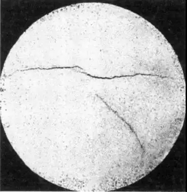
Decarburization
Decarburized carbide products exhibit white bright spots or shiny streaks on the surface, with silver-white shiny spots or tadpole-shaped pits visible on the fracture surface. The microstructure may show the presence of the η phase. Decarburization generally affects the performance of the product, and decarburized carbide products should be returned to the production unit for reprocessing.
Causes of Decarburization
1.Decarburization reaction during hydrogen sintering
The reaction between WC in the product and H? generates CH?. This reaction occurs throughout the sintering process and intensifies as the temperature rises.
At the furnace entrance, before complete shrinkage, decarburization occurs both internally and externally in the product.
At the furnace exit, after the product has shrunk, decarburization occurs on the surface. The intensity of the reaction depends on the flow rate of H?. The CH? generated by this reaction decomposes at high temperatures, causing carburization of the product.
Moisture in the furnace atmosphere reacts with WC or C at temperatures above 825°C:
H2O+WC→W+H2+CO
H2O+C→CO+H2
This reaction also occurs at both the entrance and exit of the furnace. Before complete shrinkage, it causes internal and external decarburization, while at the furnace exit, it causes surface decarburization.
Decarburization reaction during vacuum sintering
The deoxidation reaction during vacuum sintering occurs because the pressed blank contains oxygen, which is reduced by free carbon and carbon in WC during sintering. The reactions are:
MeO+C→Me+CO
MeO+2C→MeC+CO
This reaction also occurs at both ends of the furnace entry and exit. Before complete contraction, the U-shaped product causes decarburization both inside and outside. At the exit end, it causes decarburization on the product’s surface.
2.Vacuum sintering decarburization reaction
The deoxidation reaction after vacuum sintering occurs because the compact contains oxygen, which is reduced by free carbon and carbon in WC during sintering. The reaction is: MeO + C == Me + CO, MeO + 2C == MeC + decarburization reaction has occurred.

Mixing
The surface of the alloy product mixed with materials resembles the skin of a bitter melon, with uneven alloy structure. Its cross-section is different from the general dirty holes, often showing spots of varying sizes and shapes, as well as uneven surfaces. Different grades of organizational structure can be seen in the microstructure. Mixed carbide materials affect performance and are generally considered scrap, but slightly mixed materials can be inspected and treated according to the standard for cross-sectional contamination.
Causes of mixing
1.Mixing before pressing
2.The influence of certain impurity elements, such as aluminum, sulfur, silicon, phosphorus, and boron, which can cause WC grain growth during liquid-phase sintering, with phosphorus having the most significant effect.
Over-sintering
Over-sintering products have enlarged surface grains and coarser cross-sectional structure. In mild cases, only a larger number of shiny spots are observed, while in severe cases, the surface sometimes shows blisters or a honeycomb appearance. Over-fired products should be considered scrap.
Causes of over-sintering
1.Excessive sintering temperature – grain growth
2.Prolonged holding time – grain growth
Under-sintering
Under-fired alloy products have a loose structure, dark surface color, and no metallic luster. Vacuum-sintered products have a gray-white surface, larger shiny spots on the cross-section, and a noticeable water absorption phenomenon. Under-fired products should be returned to the production unit for treatment.
Poor pressing
This type of alloy product, due to insufficient compacting density and excessively large hole size, does not completely disappear during the sintering process. The product’s surface shows loose particles, mainly appearing at the blade edges and corners. In severe cases, fine cracks appear on the surface, and the cross-section shows triangular or strip-shaped holes. If only the surface is slightly poorly pressed, and the cross-section and metallography do not show this phenomenon, it can be released as a qualified product. If the surface is poorly pressed, and the cross-section and metallography also show this phenomenon, then this type of product should be treated as scrap.
Causes of poor pressing
Overly hard, overly coarse granular materials, uneven distribution of granular materials in the mold cavity, low compact single weight, low pressing pressure, or local low density.
Conclusione
The above only analyzes several reasons for the non-conformance of carbide products. In actual production, there may be various other issues, which require us to further improve our understanding, analyze the causes, and propose specific countermeasures. After the occurrence of non-conformance, it is necessary to seriously analyze our production process, identify the causes, and make improvements. Generally, attention should be paid to details, especially the usual practices that are often taken for granted. Only by truly focusing on the details can we reduce problems and avoid quality issues. Therefore, it is said: “Details determine success or failure.”
]]>introduzione
Ordinary wood screws are widely used in the furniture manufacturing industry. Most wood screws are made of Q235A steel and are formed by cold extrusion, offering advantages such as low cost, high efficiency, and large-scale production. Although screws used in the human body are structurally similar to ordinary wood screws, they must possess certain strength and corrosion resistance. Medical screws made from 1Cr18Ni9Ti stainless steel are difficult to produce via cold extrusion on dedicated machines due to material properties, small-batch production, and the need for specialized tools.
Challenges in Machining Medical Screws
For small-batch production of medical screws, CNC machining can be used to compensate for the limitations of dedicated machines. Medical screws have small diameters and relatively large pitches, resulting in poor rigidity. When using forming tools on conventional lathes, the cutting resistance increases as the tool’s cutting depth increases. Due to the small diameter and long length of medical screws, even with supporting methods to counteract most of the cutting resistance, deformation often occurs, making machining difficult. CNC machining offers high efficiency and strong adaptability. Using macro programs for thread turning ensures that the contact area between the tool and the workpiece remains constant, preventing an increase in cutting resistance with deeper cuts. However, medical screws with poor rigidity are still prone to deformation and bending. This paper conducts an in-depth study on the machining of stainless steel medical screws, addressing the challenges of machining stainless steel through reasonable process settings on CNC lathes. By designing supporting fixtures and programming macros for layered turning, the issue of insufficient rigidity in thread processing is resolved.
Principles of CNC Machining for Medical Screws
The key to producing qualified parts lies in the rational planning of the toolpath based on the geometric characteristics of medical screws. CNC machining of threads uses coated carbide inserts. The appropriate spindle speed for turning medical screws must be calculated based on the insert’s allowable cutting speed (v) to ensure reasonable tool life. The formula is:
v=nD/1000
Where:
v is the cutting speed (m/min),
D is the workpiece diameter (mm),
n is the spindle speed (r/min).
In medical screw thread machining, the main cutting force accounts for over 90% of the machine’s total power consumption, while the feed resistance accounts for over 5%. If forming tools are used on CNC machines, the contact area between the tool and the workpiece increases with cutting depth, leading to higher cutting resistance. This can cause vibration, deformation, and bending of the workpiece, making machining impossible.
Therefore, traditional forming tools cannot meet the requirements for machining medical screws. To address this, the machining method is improved by using a 35° profiling turning tool. By programming macros to control the toolpath according to the thread profile, the tool completes the profile before performing layered cuts. This ensures that the contact area between the tool and the workpiece remains constant, and the cutting force remains stable and small, overcoming the drawback of increasing cutting resistance with traditional forming tools.
Implementation of CNC Machining for Medical Screws
Selection of Tool Materials
Medical screws are primarily used to connect artificial joints and bones, requiring strength and corrosion resistance. Therefore, 1Cr18Ni9Ti stainless steel, which is acid-resistant, alkali-resistant, and corrosion-resistant, is chosen. This stainless steel has high strength, significant plasticity, and severe hardening during machining, resulting in high cutting resistance and a tendency for deformation. Additionally, the tool is subjected to high cutting temperatures, leading to built-up edge formation.
Due to the tendency of medical screws to undergo work hardening, making machining difficult, tool inserts with low adhesion, high heat resistance, wear resistance, and thermal conductivity should be selected. Adequate cooling during machining is essential, and water-based cutting fluids with good heat dissipation properties are recommended.
Structure and Dimensions of Medical Screws
As shown in Figure 1, the medical screw specifications are M6-2.5mm × 55mm, with an outer diameter of 6mm, a pitch of 2.5mm, a root width of 0.4mm, a crest width of 0.05mm, a thread angle of 60°, a length of 55mm, and a maximum diameter of 11mm at the right end. Due to the poor rigidity of the part and the relatively large pitch compared to the diameter, challenges exist in enhancing workpiece clamping rigidity and programming CNC macros.


Machining Process
Medical screws are produced in small batches. If a conventional one-clamp-one-center method is used for thread turning, the poor rigidity of the workpiece makes it unable to withstand the cutting forces, leading to bending deformation in the middle. Therefore, the workpiece must be fully supported during thread turning to ensure stability and prevent deformation. A dedicated supporting fixture is designed to assist in supporting the screw.
To reduce cutting resistance and prevent deformation during thread turning, a 35° profiling turning tool with titanium carbide coating is selected. A macro program is written using the trajectory synthesis method for layered thread cutting, significantly reducing cutting resistance and maintaining stability.
The machining process for medical screws is shown in Figure 2. The specific steps are:
Two parts are machined together, with an extra 15mm in the middle for self-centering chuck clamping and 7mm at each end for center drilling.
Turn the 6mm and 11mm outer diameters using a one-clamp-one-center method.
Clamp the 6mm outer diameter and remove the process heads, eliminating the center holes and allowing complete taper turning at both ends.
Clamp the 11mm outer diameter, support the 6mm outer diameter with the fixture, and turn the threads using the macro program.
Cut the two connected screws and trim them to ensure a 60mm length.
Use a horizontal milling machine with a vertical rotary table to clamp the part and mill a 1.5mm wide slot with a saw blade cutter.


Working Principle of the Thread Girando Support Fixture
As shown in Figure 3, the thread turning support fixture supports the medical screw during machining. Two screws are machined together to facilitate small-batch production. The support sleeve is made of HT200 gray cast iron, which has a low friction coefficient. The protrusion on the support sleeve provides axial positioning, while two screws connect and secure the support sleeve to the fixture body. The left end of the fixture body positions the support sleeve, and the right end has a standard Morse taper No. 5. The fixture is mounted on the CNC lathe’s tailstock, and the tailstock is moved during thread turning to support the screw’s outer diameter, effectively counteracting the cutting resistance. CNC thread turning is shown in Figure 4.


Machining Precautions and Quality Inspection
During the machining of medical screws, the error in the 6mm outer diameter should be controlled within approximately 0.04mm. A larger error would reduce the fit between the 6mm semi-circular hole in the support fixture and the screw’s outer diameter, weakening the fixture’s support and causing vibration or deformation during turning. Additionally, the tool must remain sharp during thread turning, and tool changes should be avoided to prevent thread misalignment.
The 6mm outer diameter of the medical screw is measured with a micrometer, the thread pitch is measured with a caliper, and the surface roughness is checked with a comparator to ensure it meets the Ra 3.2μm requirement. After inspection, the parts fully meet the dimensional requirements and are suitable for use.
Conclusione
Through the analysis of CNC machining principles for medical screws, the design of supporting fixtures, and the programming of macros, the CNC machining of medical screws has been successfully implemented, addressing the shortcomings of cold extrusion for ordinary screws. This method achieves small-batch production of medical screws at a lower cost, providing a reference for machining similar screws made from special materials.
]]>Electrolytic Grinding of Carbides
Electrolytic grinding combines electrochemical machining and mechanical grinding to process carbides, with electrochemical machining playing the dominant role (80%-90%), while mechanical grinding accounts for only 10%-20%. The productivity of this method is 4-8 times higher than conventional mechanical grinding. Additionally, it allows for easy adjustment of electrical parameters, merging rough and fine machining into a single step, thereby shortening production cycles and reducing costs. This makes electrolytic grinding an ideal method for machining carbides.
Structure and Principle
Electrolytic grinding primarily consists of three main components: a DC power supply, a machine tool, and a hydraulic system, as shown in Figure 1.

During electrolytic grinding, the carbide?workpiece is connected to the positive pole of the DC power supply, while the diamond conductive grinding wheel is connected to the negative pole. A certain contact pressure is maintained between the two, and an electrolytic gap is preserved between the workpiece and the protruding abrasive particles (diamond) on the grinding wheel. Electrolyte is supplied into this gap. When the power is turned on, an electrochemical reaction occurs on the workpiece surface, causing the carbide?to electrolyze and form a thin oxide layer (electrolytic film) on its surface. This oxide layer is much softer than the carbide?itself. The high-speed rotating diamond grinding wheel continuously removes this oxide layer, which is then carried away by the electrolyte. This exposes a fresh surface of the workpiece, allowing the electrolytic reaction to continue. The alternation between electrolysis and oxide layer removal results in the continuous machining of the carbide, forming a smooth surface with precise dimensions.
Electrochemical Reactions in Electrolytic Grinding of Carbides
carbides are primarily composed of hard carbides (WC, TiC) with a metal binder (Co), formed through pressing and sintering. According to electrochemical reactions, cobalt begins to dissolve at 1.2V, forming Co(OH)?:
?
Tungsten carbide starts to dissolve at 1.7V, while titanium carbide begins to dissolve at 3.0V:

The electrolytic efficiency is the percentage of theoretical electrolysis to actual electrolysis. In electrolytic grinding, the electrolytic efficiency of carbides ranges from 70% to 90%.
Machining Parameters
Power Supply
The power supply for electrolytic grinding is a DC source with a voltage range of 4-14V and a current range of 50-3000A. The machining gap is approximately 0.03mm (roughly equal to the size of the abrasive particles).
Electrolyte
Electrolytic grinding is based on electrochemical dissolution. The choice of electrolyte significantly affects productivity, precision, and surface quality. After extensive testing, the following three electrolyte compositions were selected:
Electrolyte 2:
NaNO?: 6.3%, NaNO?: 0.3%, Na?HPO?: 2%, pH: 8-9, Na?B?O?: 1.4%, H?O: 90%
Electrolyte 3:
NaNO?: 5%, NaNO?: 1.6%, Na?HPO?: 1%, pH: 7-8, Na?B?O?: 1.5%, NaCl: 0.05%, C?H?(OH)?: 0.3%, H?O: Balance
The electrolyte is used at a temperature of 22-30°C and a pressure of 14-70kPa. The filter precision is 50-100μm, and the nozzle, installed close to the workpiece, is equipped with an air scraper.
Diamond Electrolytic Grinding Wheel
Diamond conductive grinding wheels are typically used for electrolytic grinding of carbides due to their regular shape, high hardness, and ability to maintain a consistent electrolytic gap, resulting in high productivity. During fine grinding, mechanical grinding can be performed independently. Diamond electrolytic grinding wheels can be categorized into metal-bonded and electroplated diamond wheels. The former is used for flat and cylindrical grinding of carbide?molds, while the latter is used for electrolytic form grinding of large batches of single-shaped workpieces and internal cylindrical grinding of small holes. The grinding pressure is generally around 30N/cm2. The linear speed of the grinding wheel is typically 1200-2100 m/min, and the contact length with the workpiece should not exceed 19mm to prevent electrolyte boiling.
Material Removal Rate and Precision
The material removal rate of carbides is proportional to the current density. Under specific alloy materials, electrolyte combinations, and electrolyte boiling points, the current density is limited by the anode dissolution rate. The productivity of electrolytic grinding of carbides is generally 0.16cm3 per 100 A/min. At a current density of 77.5A/cm2, the feed rate for face grinding is 25mm/min, with a typical dimensional accuracy of ±0.025mm per pass. If an additional mechanical grinding pass is performed without electrolysis, the accuracy can reach ±0.002mm. When grinding external contours, the corner radius on the workpiece is about 0.025mm, while the roundness radius for internal contours is limited to 0.25-0.38mm. The material removal rate in electrolytic grinding is 4-8 times higher than that of conventional grinding methods.
Surface Quality
The surface roughness achieved by electrolytic grinding of carbides is generally Ra 0.2-0.8μm, but it can reach Ra 0.025-0.1μm. The surface of the workpiece resembles that obtained by metallographic polishing, and the hardness of the workpiece does not affect the surface quality. During machining, the processed surface does not develop internal stresses or heat-affected zones, resulting in high surface integrity.
Equipment and Tools
The grinding machine must have sufficient rigidity to maintain precision even under a bending stress of 1 MPa between the grinding wheel and the workpiece. The machine requires corrosion-resistant accessories for pressurizing and filtering the electrolyte. Control equipment, fixtures, and mechanical and electrical systems should be made of suitable materials or coated to operate in a salt spray environment. Conductive diamond grinding wheels are preferred for electrolytic grinding, although non-conductive abrasive wheels can also be used, albeit with less effectiveness. The electrolyte nozzle is typically made of heat-resistant organic glass or equivalent insulating materials. Workpiece fixtures are made of copper or copper alloys. The design should ensure that the cathode and anode parts are insulated during electrolytic grinding to maintain proper machine operation.
Discussion of Key Process Parameters
Current Density and Voltage
In electrolytic grinding, current density is the primary factor determining productivity. Productivity increases with higher current density, but excessively high or low current densities can reduce machining precision and surface quality. In practice, voltage should not be increased indefinitely, as excessively high voltages can cause spark discharge, affecting surface quality. For carbide?electrolytic grinding, the optimal current density is 110 A/cm2, with practical current densities ranging from 15-60 A/cm2 and voltages from 7-10V. For rough grinding, the current is 120-300 A/cm2, while for fine grinding, it is 5-6 A/cm2.
Machining Gap
At a given voltage, a smaller machining gap results in higher current density, increased productivity, and improved surface flatness and precision. However, if the gap is too small, the electrolyte may not distribute evenly, leading to spark discharge and increased wheel wear. The typical machining gap is 0.025-0.05mm.
Grinding Pressure
Increasing grinding pressure enhances productivity, but excessive pressure reduces the electrolytic gap, increasing the risk of spark discharge. Conversely, insufficient pressure leads to incomplete removal of the oxide layer, reducing both efficiency and surface quality. Therefore, grinding pressure should be set to avoid spark discharge while ensuring complete oxide layer removal. The recommended grinding pressure is 0.2-0.5 MPa.
Contact Area Between Workpiece and Grinding Wheel
A larger contact area allows the DC power supply to deliver higher current, increasing productivity while maintaining good surface quality. Therefore, during electrolytic grinding, the grinding wheel and workpiece should maintain the largest possible contact area.
Grinding Wheel Speed
Increasing the grinding wheel speed ensures adequate and rapid electrolyte supply in the gap, enhancing mechanical grinding and productivity. However, the speed should not be excessively high. The typical linear speed of the grinding wheel is 1200-2100 m/min.
Electrolyte Supply
The electrolyte flow rate should ensure sufficient and uniform entry into the machining gap. For vertical electrolytic surface grinders, the flow rate is typically 5-15 L/min, while for cylindrical grinders, it is 1-6 L/min. The installation of the electrolyte nozzle is crucial, as it helps confine the electrolytic action to the machining gap between the grinding wheel and the workpiece. The nozzle must be firmly installed close to the outer surface of the grinding wheel and equipped with an air scraper to break the air layer on the rotating wheel’s outer edge. The electrolyte pressure is generally 14-70kPa, and the temperature is controlled between 19-33°C.

Conclusione
High Productivity
Electrolytic grinding of carbides offers 4-8 times higher productivity than conventional mechanical grinding, especially when the contact area between the conductive diamond grinding wheel and the carbide?workpiece is increased.
Excellent Surface Quality
Electrolytic grinding of carbides achieves high surface quality, with typical surface roughness of Ra 0.4μm or better, and can reach Ra 0.025μm, producing a mirror-like finish. Increasing the machining current does not significantly affect surface quality. Additionally, the processed surface does not develop internal stresses or heat-affected zones, resulting in high surface integrity unmatched by other machining methods.
High Precision
With advancements in carbide?electrolytic grinding, the use of diamond electrolytic grinding wheels that can perform both electrolytic and mechanical grinding allows for high precision. After electrolytic grinding, the power can be turned off, and mechanical grinding can be performed to achieve precision comparable to conventional mechanical grinding.
Low Grinding Wheel Wear
In electrolytic grinding, the abrasive particles in the grinding wheel primarily maintain the electrolytic gap and remove the oxide layer, reducing abrasive wear. The wear of diamond grinding wheels in electrolytic grinding is significantly lower than that in conventional mechanical grinding.
In summary, electrolytic grinding of carbides offers unique advantages over conventional machining methods, significantly improving productivity, surface quality, and precision, making it an ideal method for machining carbides.
]]>Because machine tools have systematic mechanical-related deviations that can be recorded by the system. However, due to environmental factors such as temperature or mechanical load, these deviations may still occur or increase during subsequent use.

Backlash Compensation
When transmitting force between the moving components of a machine tool and its driving components—such as ball screws—interruptions or delays can occur. This is because a completely gap-free mechanical structure would significantly increase machine tool wear and is also difficult to achieve from a technical standpoint. Mechanical gaps cause deviations between the motion path of the axis/spindle and the measurements from the indirect measurement system. This means that once the direction changes, the axis will move either too far or not far enough, depending on the size of the gap. The worktable and its associated encoder are also affected: if the encoder position leads the worktable, it reaches the commanded position prematurely, meaning the actual distance moved by the machine tool is shortened. During machine operation, by using the backlash tool compensation function on the corresponding axis, the previously recorded deviation is automatically activated when the direction changes, and this deviation is added to the actual position value.
Screw Pitch Error Compensation
The measurement principle of indirect measurement in CNC control systems is based on the assumption that the pitch of the ball screw remains constant over its effective travel range. Therefore, in theory, the actual position of the linear axis can be derived from the motion information of the drive motor.。

However, manufacturing errors in the ball screw can lead to deviations in the measurement system (also known as screw pitch errors). Measurement deviations (depending on the measurement system used) and installation errors of the measurement system on the machine tool (also referred to as measurement system errors) may further exacerbate this issue. To compensate for these two types of errors, an independent measurement system (such as laser measurement) can be used to measure the natural error curve of the CNC machine tool. The required tool compensation values are then saved in the CNC system for tool compensation.

Friction Compensation (Quadrant Error Compensation) and Dynamic Friction Compensation
Quadrant error compensation (also known as friction compensation) is suitable for all the aforementioned scenarios to significantly improve contour accuracy when machining circular profiles. The reason is as follows: During quadrant transitions, one axis moves at the maximum feed rate while the other axis remains stationary. As a result, the different friction behaviors of the two axes can lead to contour errors. Quadrant error tool compensation effectively reduces this error and ensures excellent machining results. The density of tool compensation pulses can be set based on an acceleration-related characteristic curve, which can be determined and parameterized through roundness testing. During roundness testing, deviations between the actual position of the circular contour and the programmed radius (especially during direction changes) are quantified and graphically displayed on the human-machine interface.
In newer versions of the system software, the integrated dynamic friction tool compensation function dynamically compensates for friction behavior at different machine speeds, reducing actual machining contour errors and achieving higher control accuracy.
Sag and Angular Error Compensation

If the weight of individual components of the machine tool causes displacement or tilting of moving parts, sag tool compensation is required because it can lead to sagging of relevant machine tool parts, including the guiding system. Angular error tool compensation is used when moving axes are not correctly aligned with each other (e.g., not perpendicular). As the offset from the zero position increases, the positional error also increases. Both types of errors are caused by the machine tool’s own weight or the weight of the tool and workpiece. During commissioning, the measured tool compensation values are quantified and stored in the SINUMERIK system in a form such as a compensation table, corresponding to specific positions. During machine operation, the positions of the relevant axes are interpolated based on the stored tool compensation values. For each continuous path movement, there is a base axis and a compensation axis.
Temperature Compensation
Heat can cause expansion in various parts of the machine tool. The extent of expansion depends on factors such as the temperature and thermal conductivity of each part. Different temperatures may cause changes in the actual positions of the axes, which can negatively impact the accuracy of the workpiece being machined. These changes in actual values can be offset through temperature tool compensation. Error curves for each axis at different temperatures can be defined. To ensure accurate compensation for thermal expansion, temperature compensation values, reference positions, and linear gradient parameters must be continuously transferred from the PLC to the CNC control system via functional blocks. Unexpected parameter changes are automatically corrected by the control system to prevent machine overload and activate monitoring functions.
Volumetric Compensation System (VCS)

The positions of rotary axes, their mutual tool compensation, and tool orientation errors can lead to systematic geometric errors in components such as turrets and rotary heads. Additionally, small errors may occur in the guiding systems of feed axes in every machine tool. For linear axes, these errors include linear position errors, horizontal and vertical straightness errors; for rotary axes, pitch, yaw, and roll errors may arise. Other errors, such as perpendicularity errors, can occur when aligning machine components. For example, in a three-axis machine tool, this can result in up to 21 geometric errors at the tool center point (TCP): six error types per linear axis multiplied by three axes, plus three angular errors. These deviations collectively form the total error, also known as the volumetric error.
The volumetric error describes the deviation between the actual TCP position of the machine tool and the TCP position of an ideal, error-free machine tool. SINUMERIK solution partners can determine volumetric errors using laser measurement equipment. Measuring errors at a single position is insufficient; errors across the entire machining volume must be measured. Typically, measurement values for all positions are recorded and plotted as curves, as the magnitude of errors depends on the position of the relevant feed axis and the measurement location. For example, deviations in the x-axis may vary when the y-axis and z-axis are in different positions—even at nearly the same x-axis position. With “CYCLE996 – Motion Measurement,” rotary axis errors can be determined in just a few minutes. This allows for continuous monitoring of machine tool accuracy and, if necessary, corrections can be made even during production.
Deviation Compensation (Dynamic Feedforward Control)
Deviation refers to the discrepancy between the position controller and the standard during the movement of a machine tool axis. Axis deviation is the difference between the target position and the actual position of the axis. Deviation causes speed-related unnecessary contour errors, especially when the contour curvature changes, such as in circles, squares, or other shapes. Using the NC advanced language command FFWON in the part program, speed-related deviations can be reduced to zero during path movement. Feedforward control improves path accuracy, resulting in better machining outcomes.

FFWON: Command to activate feedforward control
FFWOFF: Command to deactivate feedforward control
Electronic Counterbalance Compensation
In extreme cases, to prevent damage to the machine tool, tool, or workpiece caused by axis sagging, the electronic counterbalance function can be activated. In load axes without mechanical or hydraulic counterbalances, a vertical axis may unexpectedly sag once the brake is released. After activating the electronic counterbalance, unintended axis sagging can be compensated. Upon releasing the brake, a constant balancing torque maintains the position of the sagging axis.
]]>
Carbide Manufacturing Process
The process involves weighing ultra-fine WC powder and Co powder, produced by special methods, according to the composition ratio, and adding small amounts of elements such as Ti, Ta, Nb, and Cr. Wet grinding is performed using φ8 cemented carbide balls with a ball-to-material ratio of 5:1. The grinding medium is anhydrous alcohol, and the grinding time ranges from 72 to 120 hours. The slurry is dried at 80 to 100°C for about 2 to 4 hours, then mixed with glue (wax) to form granules. These are pressed into various products such as 5×5×30 and A118A, and sintered under H? protection at temperatures between 1400°C and 1500°C.
Microstructure and Physical-Mechanical Properties
Due to the use of special raw materials and production methods different from conventional processes, and the appropriate selection of types and quantities of added elements, the YT04 carbide achieves the desired effects. Table 1 lists the performance indicators of the YT04 carbide grade from several developments, and Figure 1 shows the metallographic structure of the YT04 carbide.

From the results in Table 1 and Figure 1, the YT04 carbide has high hardness and moderate strength. The microstructure is very uniform, with grain sizes almost all less than 0.5 μm, except for a few WC grains larger than 0.5 μm. The thickness of the binder phase is also less than 0.5 μm.

Cutting Characteristics
Application Range of YT04 carbide
Due to its extremely fine WC grain size and high hardness, the YT04 carbide has very high wear resistance, red hardness, and thermal strength, along with high strength. This carbide is suitable for machining difficult materials such as ferrosilicon, vanadium-titanium cast iron, boron-added cast iron, white cast iron, high, medium, and low nickel-chromium chilled cast iron; various quenched carbide steels, tool steels, magnetic steels, high manganese steels, ultra-high strength steels, high-speed steels; tungsten-based, molybdenum-based, titanium-based non-ferrous carbides; granite, marble, glass, cast stone, high-cobalt cemented carbide, steel-bonded cemented carbide, and some ceramic materials and engineering plastics for precision turning, milling, planing, and cutting. It can also be used for semi-finishing, with a durability 1 to 10 times higher than traditional YT, YG, and YM grade cemented carbides. The surface finish of the machined workpiece can reach up to ▽8. It shows particularly satisfactory results when used for low-speed cutting to replace high-speed steel tools.
Usage Conditions of YT04
According to relevant literature, the YT04 carbide should be used with the following parameters:
(1) Main cutting edge angle (K,) ≤ 45°.
(2) Rake angle (Y.) = 0 to -8°, cutting edge inclination angle (λ) = -5 to -9°.
(3) Clearance angle (a.) and tool nose radius (Ye). Since the YT04 carbide is only suitable for finishing and semi-finishing, a larger clearance angle should be chosen to reduce friction between the flank face and the workpiece surface, typically around 10°. The tool nose radius should be 1 to 2 mm.
(4) Cutting speed (V). The cutting speed should be determined based on specific conditions. For workpieces with HRC60 and above, a cutting speed of 10 m/min is ideal, and should not exceed 20 m/min to avoid tool tip reddening and burning. For materials around HRC45, the cutting speed can be increased to about 50 m/min, but should not exceed 100 m/min to fully utilize the tool’s excellent performance. For materials like 35CrMoA (HB≈229), the cutting speed can even be as high as 200 m/min or more.
(5) Depth of cut (αp). This depends on the surface quality requirements of the workpiece. For a finish of 76 or above, the cutting depth can be set at 0.07 to 0.12 mm. If the precision requirements are not strict, it can be set at 0.2 to 0.4 mm.
(6) Feed rate (f). YT04 is generally used for finishing, with a feed rate typically of 0.2 to 0.3 mm. For semi-finishing, the feed rate can be increased to 0.4 to 0.5 mm. It should be noted that if machining high-hardness materials around HRC65, too large a feed rate can cause chipping.
Cutting Examples
Here are some examples of YT04 carbide in practical use:
- Material: Cast stone, workpiece size: Φ160×1500, external turning, tool geometry parameters: K,=45°, Y.=12°, α=6°, λ=-6°; cutting parameters: V=6 m/min, f=0.1 mm/r, ap=1.00 mm.
- Material: Quenched bearing steel, HRC62, workpiece: Φ30×50 mm, external turning; tool geometry parameters: K=40°, Y.=15°, α.=10°, Re=0.5 mm. Cutting parameters: V=61.8 m/min, f=0.14 mm/r, αp=0.4 mm. Test results: After machining 11 pieces per cutting edge, the cutting path reached 2472 m, with basically no wear on the cutting edge, and a workpiece surface finish of 76.
Usage Instructions
1.Strictly follow the provided tool geometry parameters and cutting conditions.
2.YT04 carbide is not suitable for intermittent cutting.
3.YT04 carbide can be sharpened with green silicon carbide wheels. Using diamond oil stones for edge honing can further improve performance.
Conclusione
Overall, the YT04 carbide, with its extremely fine grain size and excellent physical-mechanical properties, performs exceptionally well in machining difficult-to-process materials and is suitable for various precision machining applications.
]]>
Sample Preparation and Experimental Conditions
Material Selection
To compare the corrosion resistance of WC-based cemented carbides, four groups of test materials were selected:
(1) WC-Co alloy;
(2) WC-Co alloy with a small amount of heterogeneous carbides;
(3) WC-Ni·Mo·Co·Cr alloy;
(4) Low binder phase content alloy.
Corrosion Conditions
Corrosion Media: Hydrochloric acid, sulfuric acid, nitric acid, citric acid (H?Cit), acetic acid (HAC), sodium hydroxide (50%), and potassium hydroxide (50%).
Test Temperatures: 20°C, 40°C, 80°C, and boiling point. Alkali solutions were only tested at the boiling point.
Corrosion Time: 24-72 hours for low temperatures and 6-24 hours for the boiling point.
Corrosion Rate Calculation: The corrosion rate (A) is calculated as the amount of material corroded per unit area per day, expressed in mg/dm2·day (abbreviated as mdd).
Results and Discussion
Relationship Between Corrosion Rate and Binder Phase Content in WC-Based Cemented Carbides
The corrosion rate of WC-based cemented carbides is related to the content of the binder phase, regardless of the binder’s composition. Alloys with higher binder content exhibit higher corrosion rates. For WC-Co alloys, when the cobalt content exceeds 2%, the corrosion rate increases sharply. In 5% HNO?, the corrosion rate of WC-2% Co alloy still exceeds the acceptable limit. However, the corrosion rate of WC-Ni·Mo·Co·Cr alloy with 2% Ni·Mo·Co·Cr meets the usage requirements under all tested conditions. Even in highly corrosive nitric acid, its corrosion rate is only 196.6 mdd, corresponding to corrosion resistance grade B (less than 250 mdd).
The difference in corrosion rates among alloys with varying cobalt content is not significant at room temperature. However, as the temperature increases, the difference becomes more pronounced. At room temperature, increasing the cobalt content from 2% to 20% results in a corrosion rate change of only 12-30 mdd. At the boiling point, the corrosion rate increases from 20 mdd for low cobalt content to 6×10? mdd for high cobalt content.
Effect of WC Grain Size on Corrosion Rate
Fine-grained alloys have higher interfacial energy and greater internal stress in the binder phase, resulting in lower corrosion resistance. Therefore, fine-grained alloys are not recommended for improving resistance.
Effect of Small Amounts of Heterogeneous Carbides on Corrosion Rate
Comparing WC-Co cemented carbides with small amounts of heterogeneous carbides reveals that their effects on corrosion rates vary:
Cr?C?: A small amount of Cr?C? can improve the alloy’s corrosion resistance. Even though alloy No. 9 has finer WC grains than alloy No. 4, its corrosion resistance is superior due to the addition of Cr?C?.
TaC: The addition of a small amount of TaC has no significant effect on resistance. Comparing alloy No. 4 with alloy No. 7 (which contains 2% TaC), the corrosion rates are similar. Adding 5% TaC also does not improve corrosion resistance.
Mo?C: Adding less than 1% Mo?C can significantly enhance resistance. This is because Mo?C readily dissolves in the γ phase, thereby improving the alloy’s corrosion resistance.
Thus, adding small amounts of Cr?C? or Mo?C is beneficial for improving the corrosion resistance of cemented carbides.
Effect of Graphite and η1 Phase on Alloy Corrosion Rate
The presence of graphite and η1 phase not only significantly affects the physical and mechanical properties of the alloy but also has a notable impact on the corrosion rate. For the tested media, the presence of graphite significantly reduces the alloy’s corrosion resistance. When graphite is present, the solubility of tungsten (or molybdenum) in the binder phase drops below 2-3%, reducing the binder phase’s resistance. Additionally, according to corrosion theory, graphite increases the electrochemical corrosion effect of micro-galvanic cells between phases. Therefore, cemented carbides used as corrosion-resistant materials must avoid the formation of graphite.
In contrast, the η1 phase significantly enhances the alloy’s corrosion resistance. The presence of η1 phase indicates carbon deficiency in the alloy, allowing the binder phase to dissolve a large amount of W (or Mo), typically 10-13%. This composition of the binder phase is more corrosion-resistant. Moreover, the transformation of a certain amount of binder into η1 phase further improves the alloy’s resistance. Thus, under carbon-deficient conditions, the alloy’s corrosion resistance increases sharply compared to normal alloys.
Given these findings, the carbon content should be controlled at the lower limit of the two-phase region or allow the formation of a small amount of dispersed η1 phase, provided that the mechanical properties are not excessively compromised. This results in an ideal microstructure with high corrosion resistance.
Relationship Between Binder Phase Corrosion Resistance and Alloy Corrosion Rate
While the mechanical properties of WC-Ni alloys are generally lower than those of WC-Co alloys, their corrosion resistance is superior, especially under low-carbon conditions. However, alloys with pure nickel as the binder often fail to meet usage requirements, leading to the development of complex nickel-based binders. Ni-Mo alloys exhibit excellent resistance to acid and alkali corrosion, making them suitable as binders for WC-based alloys. This study tested the corrosion resistance of alloys with Ni-Mo-Co-Cr (83:15:1:1) as the binder. The overall trend in corrosion rates for this series is similar to that of WC-Co alloys, but the values are significantly lower. Particularly, low binder content alloys meet the specified usage requirements for all tested media, with corrosion rates below 250 mdd. Additionally, the corrosion rate of WC-Ni·Mo·Co·Cr alloys does not change significantly with increasing temperature.
In summary, improving the corrosion resistance of WC-based cemented carbides depends on enhancing the binder phase’s corrosion resistance, which is particularly effective for low binder content alloys.
Activated Sintering of WC-Based Low Binder Content Alloys
An important approach to improving the resistance of WC-based cemented carbides is to reduce the binder content, provided that the physical and mechanical properties meet usage requirements.
To enhance the performance of sintered products, activated sintering is often employed. The properties of low binder content alloys are closely related to the uniformity of component mixing. Therefore, chemical mixing to produce composite powders, intensified ball milling, and activated sintering processes were adopted. For comparison, conventional processes were also used to prepare alloys with the same composition.
Comparison of Corrosion Resistance Among Different Alloys
Corrosion rates are classified into three grades: A (<25 mdd), B (<250 mdd), and C (<500 mdd). For WC-Co alloys, only low binder content alloys exhibit comprehensive corrosion resistance. In contrast, WC-Ni·Mo·Co·Cr alloys maintain considerable corrosion resistance even with 10% binder content. Notably, WC-2% Ni·Mo·Co·Cr alloys demonstrate excellent resistance under all tested conditions.
WC-Ni·Mo·Co·Cr alloys are widely used in manufacturing ballpoint pen tips. These alloys outperform traditional WC-Co·Ni·Cr alloys in various properties, are easier to produce, and have lower production costs, making them ideal materials for corrosion-resistant ballpoint pen tips.

Conclusions
1.The corrosion resistance of WC-based cemented carbides is primarily determined by the resistance of the binder phase. Lower binder content results in better condition. Alloys with Ni·Mo·Co·Cr as the binder exhibit significantly lower corrosion rates than WC-Co alloys, especially those with low binder content.
2.The corrosion rate of WC-based cemented carbides is related to the grain size of the hard phase. Finer grains lead to poorer corrosion resistance.
3.Small amounts of heterogeneous carbides, such as Cr?C? and Mo?C, can improve the resistance of WC-Co alloys, while TaC has little to no effect.
4.Graphite reduces the resistance of WC-based alloys, whereas the η1 phase significantly enhances it. Therefore, the ideal corrosion-resistant alloy should have carbon content controlled at the lower limit of the two-phase region or allow the formation of dispersed η1 phase without excessively compromising mechanical properties.
5.Low binder content alloys with good corrosion resistance can be prepared using chemical mixing to produce composite powders, intensified ball milling, and activated sintering processes, achieving high physical and mechanical properties.
6.The study of the corrosion resistance of WC-based cemented carbides provides a basis for their broader application.
]]>
