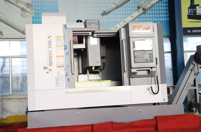
High-Speed Cutting Milling Equipment
1.High Stability of Machine Bed Components
The bed and support components of a high-speed cutting machine must exhibit excellent dynamic and static stiffness, thermal rigidity, and optimal damping characteristics. Most machines use high-quality, high-rigidity gray cast iron for these components, with some manufacturers incorporating high-damping polymer concrete into the base to enhance vibration resistance and thermal stability. This not only ensures stable machine accuracy but also prevents tool chatter during cutting. Measures such as closed bed designs, integral casting of the machine bed, symmetric bed structures, and dense ribbing are also crucial for enhancing machine stability.
2.Machine Spindle
The spindle performance of high-speed machines is crucial for achieving high-speed cutting. High-speed cutting spindles typically operate at speeds ranging from 10,000 to 100,000 RPM, with spindle power greater than 15 kW. Spindle axial gaps between the tool holder and spindle are controlled to be no more than 0.005 mm using compressed air or cooling systems. Spindles are required to have rapid acceleration and deceleration capabilities, meaning they must have high angular acceleration and deceleration rates.
High-speed spindles often use liquid static pressure bearings, air static pressure bearings, hot-pressed silicon nitride (Si3N4) ceramic bearings, or magnetic suspension bearings. Lubrication is commonly achieved with oil-air lubrication or spray lubrication, and spindle cooling typically involves internal water or air cooling.
3.Machine Drive System
To meet the demands of high-speed mould processing, the drive system of a high-speed milling machine should have the following characteristics:
High Feed Speed: Research indicates that increasing spindle speed and feed per tooth is beneficial for reducing tool wear, especially for small-diameter tools. Common feed speed ranges are 20-30 m/min, with large lead ball screws allowing speeds up to 60 m/min and linear motors achieving up to 120 m/min.
High Acceleration: High-speed milling of complex 3D surfaces requires a drive system with good acceleration characteristics, with drivers providing high-speed feed (fast feed rate of about 40 m/min and 3D profile processing speed of 10 m/min) and accelerations and decelerations ranging from 0.4 m/s2 to 10 m/s2.
Most machine manufacturers use closed-loop position servo control with small lead, large-size, high-quality ball screws or large lead multi-head screws. Advances in motor technology have led to the development and successful application of linear motors in CNC machines. Linear motor drives eliminate issues such as mass inertia, overshooting, lag, and vibrations, speeding up servo response, improving servo control accuracy, and enhancing machine processing precision.
4.CNC System
Advanced CNC systems are key to ensuring the quality and efficiency of high-speed processing of complex mould surfaces. Basic requirements for CNC systems in high-speed cutting include:
High-Speed Digital Control Loop: Includes 32-bit or 64-bit parallel processors and hard drives with over 1.5 GB; extremely short linear motor sampling times.
Speed and Acceleration Feedforward Control: Digital drive systems with jerk control.
Advanced Interpolation Methods: Such as NURBS-based spline interpolation for good surface quality, precise dimensions, and high geometric accuracy.
Look-Ahead Function: Requires a large capacity buffer register to pre-read and check multiple program segments (e.g., up to 500 segments for DMG machines, and 1000-2000 segments for Siemens systems) to adjust feed speeds and avoid over-cutting when surface shapes (curvatures) change.
Error Compensation Functions: Includes compensation for thermal errors due to linear motors and spindles, quadrant errors, measurement system errors, etc. Additionally, high data transmission speeds are required.
Data Interfaces: Traditional data interfaces like RS232 serial ports transmit at 19.2 kb, while many advanced milling centers now use Ethernet for data transmission at speeds up to 200 kb.

5.Cooling and Lubrication
High-speed milling uses coated carbide tools and operates without cutting fluids, resulting in higher cutting efficiency. This is because the high centrifugal forces of the rotating spindle make it difficult for cutting fluids to reach the cutting zone, and even if they do, the high temperatures may cause the fluids to evaporate, reducing cooling effectiveness. Additionally, cutting fluids can cause rapid temperature changes at the tool edge, leading to cracking. Thus, dry cutting with oil/air cooling is employed. This method quickly blows away the cutting heat with high-pressure air, and atomized lubrication oil forms a thin protective film on the tool edge and workpiece surface, effectively extending tool life and improving surface quality.

Tools for High-Speed Cutting
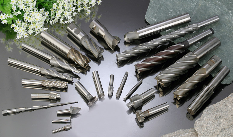
Tools are one of the most critical factors in high-speed cutting, directly impacting processing efficiency, manufacturing costs, and product precision. High-speed cutting tools must withstand high temperatures, pressures, friction, impact, and vibrations. They should have good mechanical properties and thermal stability, including impact resistance, wear resistance, and thermal fatigue resistance. The development of high-speed cutting tools has been rapid, with common materials including diamond (PCD), cubic boron nitride (CBN), ceramic tools, coated carbide, and titanium carbide (TiC) and titanium nitride (TiN) hardmetals.
For cutting cast iron and alloy steel, carbide is the most commonly used tool material due to its good wear resistance, although its hardness is lower than CBN and ceramics.
To improve hardness and surface finish, coating technologies such as titanium nitride (TiN) and aluminum titanium nitride (TiAlN) are employed. Coating technology has evolved from single-layer to multi-layer and multi-material coatings, becoming a key technology for enhancing high-speed cutting capabilities. Carbide inserts with titanium carbonitride coatings in the diameter range of 10-40 mm can process materials with Rockwell hardness below 42, while titanium aluminum nitride-coated tools can handle materials with Rockwell hardness of 42 or higher.
For high-speed cutting of steel, tools made from heat-resistant and fatigue-resistant P-class carbide, coated carbide, CBN, and CBN composite materials (WBN) are preferred. For cutting cast iron, fine-grain K-class carbide should be used for roughing, and composite silicon nitride ceramics or polycrystalline CBN (PCBN) tools for finishing.
For precision milling of non-ferrous metals or non-metallic materials, polycrystalline diamond (PCD) or CVD diamond-coated tools are recommended. When selecting cutting parameters, attention should be given to the effective diameter for round blades and ball end mills. High-speed milling tools should be designed with dynamic balancing, and the cutting edge angles should be adjusted compared to conventional tools.
High-Speed Milling Processes and Strategies
High-speed machining includes roughing, semi-finishing, finishing, and mirror finishing to remove excess material and achieve high-quality surface finishes and fine structures.
Rudesse
The primary goal of mould roughing is to maximize material removal rate per unit time and prepare the geometric profile of the workpiece for semi-finishing. The process plan for high-speed roughing involves a combination of high cutting speeds, high feed rates, and small cutting depths. The most commonly used CAM software employs methods like spiral contouring and Z-axis contouring, which generate continuous, smooth tool paths in a single pass without retracting the tool, using arc entry and exit methods. Spiral contouring avoids frequent tool retraction and approach, minimizing the impact on surface quality and machine wear. Steep and flat areas are processed separately, with optimized tool paths generated using spiral methods with minimal retraction to achieve better surface quality. In high-speed milling, it is essential to use arc entry and exit methods and maintain a consistent tool path to minimize machine wear and achieve higher material removal rates.
Semi-Finishing
The semi-finishing process focuses on improving surface quality and dimensional accuracy, bridging the gap between roughing and finishing. The cutting speeds are higher than those used in traditional milling but lower than those in finishing. The primary goal is to achieve a better surface finish and precision by using a reduced depth of cut and controlling feed rates. Advanced CAM systems generate tool paths using techniques like trochoidal milling and adaptive clearing, which adaptively change cutting parameters based on the workpiece geometry and tool path. This method enhances tool life and surface quality while reducing cutting forces and thermal stresses.
Finition
Finishing operations aim to achieve the final surface quality and dimensional accuracy. High-speed finishing involves higher cutting speeds and lower depths of cut, using techniques such as high-speed finishing cuts with constant engagement to ensure a smooth and uniform surface. Tool paths are optimized using advanced CAM software to achieve the desired surface finish and accuracy. Techniques like high-speed trochoidal milling and constant chip load milling are used to achieve excellent surface finishes and tight tolerances.
Mirror Finishing
Mirror finishing is the final step to achieve an exceptionally smooth and reflective surface. High-speed mirror finishing processes often involve special tools and techniques, including abrasive tools and polishing compounds. The key is to minimize surface irregularities and achieve a mirror-like finish with high precision. Techniques such as high-speed burnishing, polishing, and super-finishing are employed to achieve the desired surface quality.
Conclusion
High-speed milling technology has revolutionized the mould manufacturing industry by significantly enhancing machining efficiency, precision, and surface quality. The integration of advanced machining equipment, CNC systems, tooling technologies, and innovative milling strategies has enabled the production of complex mould cavities with high accuracy and reduced processing times. As technology continues to advance, high-speed milling will play an increasingly crucial role in meeting the evolving demands of the mould manufacturing industry.


