
Sources of Waste tungsten carbides
Globally, approximately 30,000 to 50,000 metric tons of waste tungsten carbides are generated annually, with China accounting for over 40% of this volume, indicating tremendous recycling potential. Specifically, waste tungsten carbides primarily originate from the following sources:
Residual materials from worn cutting tools, such as lathe tools, milling cutters, and drill bits;
Large tungsten carbide components, including mining drill bits, molds, and rolling mill rolls;
Certain wear-resistant electronic components (e.g., semiconductor packaging materials) that contain tungsten carbides.
Recycling Methods for Waste tungsten carbides
Currently, mainstream recycling technologies include mechanical, chemical, and zinc melting processes, each with its own advantages and limitations:
Crushing Method
The mechanical crushing method is one of the simplest approaches for recycling waste tungsten carbides. It does not alter the chemical composition of the waste material and does not require separation of tungsten and cobalt. After surface cleaning, the waste tungsten carbide undergoes mechanical crushing and ball milling to produce a mixed powder with a chemical composition nearly identical to the original waste (except for a slight increase in iron content and decrease in carbon content).
For tungsten carbides with low cobalt content (which tend to have relatively lower strength), the material can be manually or mechanically crushed to a certain fineness before being ground in a wet mill to achieve the desired particle size for reuse in tungsten carbide production.
Advantages:
Simple process, short workflow
Low energy consumption
Environmentally friendly (no chemical pollution)
Limitations:
Risk of contamination from metal tool debris during manual crushing
Ineffective for high-cobalt tungsten carbides due to their resistance to crushing
Difficulty in ensuring consistent quality for recycled products made from complex carbide mixtures
Advancements in the Crushing Method
Russian researchers have developed an innovative tungsten carbide?recycling process utilizing a simple mechanical crushing approach. This method employs a novel high-power crusher—the conical inertial crusher—enabling high-quality recovery of waste tungsten carbides through crushing and fine grinding alone, without requiring any chemical treatment.
For instance, when processing waste YG6 anvils (used in synthetic diamond production), the waste anvils are first crushed in the conical inertial crusher to produce raw material for tungsten carbide?manufacturing. To enhance the performance of the crushed powder mixture, it is recommended to add 1%–2% cobalt powder, which improves compaction and sintering densification.
Currently, the crushing method continues to evolve, with the adoption of more advanced, cleaner, and efficient crushing equipment for processing waste tungsten carbides.
Zinc Melting Process for tungsten carbide?Treatment
Fundamental Principles of the Zinc Melting Process
The mechanism of the zinc melting process for tungsten carbides is based on the formation of?low-melting-point carbides?between zinc and the binder-phase metals (cobalt or nickel) in tungsten carbides at?900°C. At?896°C, the solubility of cobalt in zinc reaches?27%, allowing the binder metal to separate from the tungsten carbide?and form a?zinc-cobalt solid-solution carbide?liquid. This disrupts the tungsten carbide’s structure, leaving behind a loosely bound?hard-phase skeleton.
Since zinc does not chemically react with refractory metal carbides, and given that zinc’s vapor pressure is significantly higher than cobalt’s at specific temperatures, zinc can be?evaporated and recovered (at 925°C)?for reuse. As a result, the carbide powder obtained through the zinc melting process retains most of its original properties. After the process, cobalt or nickel is extracted into the zinc melt, while the carbides remain. The zinc is then distilled off and recycled for subsequent reuse.
Traditional zinc melting furnaces?are?vertical vacuum furnaces. The system operates under conditions ranging from?vacuum to partial-pressure atmospheres, up to just below atmospheric pressure. The components of zinc melting equipment are illustrated in?Figure 2, while the furnace’s main structure is shown in?Figure 3.


Key Characteristics of the Zinc Melting Process
The zinc melting process was invented by the British in the 1950s. Subsequently, the United States improved this process and enhanced the equipment. After the 1970s, it became widely adopted in many countries. In China, many manufacturers engaged in recycling waste tungsten carbides have mastered this method. Its main advantages are simple process, short flow, simple equipment, small investment, and low cost, making it particularly suitable for processing waste tungsten carbides with cobalt content below 10% and applicable for small enterprises to reuse waste tungsten carbides for carbide reproduction.
However, this process also has some disadvantages. First, the residual zinc content in the mixed material is relatively high. During the zinc melting and zinc recovery processes, whether the equipment is reasonable or not affects the zinc recovery efficiency. Second, the entire process consumes a large amount of electricity, with power consumption for each ton of tungsten carbide reaching approximately 6,000~12,000 kW·h. Additionally, there are environmental protection issues, as zinc emissions may have certain impacts on operators.
Currently, China’s WC-Co carbides have three tungsten carbide grain structures: coarse, medium, and fine. P-type carbides can be roughly divided into three categories based on titanium content: low-titanium, medium-titanium, and high-titanium. During recycling, it is best to strictly separate them to avoid mixing different sizes of tungsten carbide grains or zinc-melted mixed materials with different titanium contents.

Electrochemical Methods
Electrochemical methods mainly include the electrolysis method, as well as the electrolytic electrodeposition method and the electrodialysis electrolysis method developed from the electrolysis method.
Each method offers unique capabilities for metal recovery and purification from tungsten carbide waste streams.
Principle of Electrolysis Method
The electrolysis method involves directly placing waste tungsten carbides into an electrolytic cell with acids (hydrochloric acid, sulfuric acid, nitric acid, etc.) as the electrolyte. During electrolysis, the Co in the carbide transforms into Co2? and enters the solution, while the WC, having lost its binder metal cobalt, becomes a porous carbide. The cobalt-containing solution is precipitated with ammonium oxalate, and cobalt powder is obtained after calcination and reduction. The WC can be directly used in tungsten carbide production after ball milling and crushing or appropriate treatment (such as post-crushing carbon supplementation and re-carburization).
The electrolytic electrodeposition method takes advantage of the fact that hydrogen’s deposition potential is more positive than that of cobalt, causing hydrogen gas to preferentially deposit at the cathode. As the Co2? concentration increases and H? decreases, metallic cobalt is simultaneously deposited alongside hydrogen at the cathode. Thus, the electrolytic system becomes an electrolytic refining process where waste carbide serves as the anode, CoCl? as the electrolyte, and pure cobalt is deposited at the cathode.
The electrodialysis electrolysis method introduces a cation-exchange membrane into the electrolytic cell, dividing it into anode and cathode compartments. The cation-exchange membrane, a functional polymer film selectively permeable to ions, allows only cations to pass while blocking anions. Consequently, Co2? migrates through the membrane into the cathode compartment during electrolysis, while OH? accumulates in the cathode compartment due to the membrane’s barrier effect, raising the pH and resulting in Co(OH)? precipitation. Compared to conventional electrolysis, both the electrolytic electrodeposition and electrodialysis electrolysis methods shorten the cobalt recovery process and improve recovery rates.
High-Temperature Treatment Method
Principle of High-Temperature Treatment
The high-temperature treatment process is a novel recycling technology for tungsten carbides. This method involves re-sintering tungsten carbides at high temperatures to loosen their structure and promote grain growth. Subsequent mechanical crushing yields high-quality powder suitable for producing coarse-grained tungsten carbides. tungsten carbides manufactured from this powder exhibit performance metrics that meet or exceed those of standard carbide products. The high-temperature treatment process provides a new approach for recycling waste tungsten carbides and producing coarse-grained tungsten carbides.

High-Temperature Treatment Process for Waste tungsten carbides
The high-temperature treatment of tungsten carbides is conducted in specially designed high-temperature furnaces. Under a protective atmosphere at temperatures exceeding 1800°C, the waste carbide undergoes treatment where binder metals like cobalt liquefy and boil, causing carbide deformation and significant volume expansion. The carbide structure transforms into a porous, honeycomb-like formation, making the hardened carbide extremely easy to crush and process. During this high-temperature treatment:
A substantial liquid phase forms in the carbide
Atomic diffusion intensifies→
WC dissolution-precipitation effects strengthen→
WC grains grow rapidly from 1-2μm to several dozen or even hundreds of micrometers→
Defects in WC crystal structures are eliminated during recrystallization→
WC crystal structures become more complete→
Trace metal/non-metal impurities and harmful contaminants are removed
Characteristics of High-Temperature Method and Regenerated carbide Performance
This regenerated mixed material is particularly suitable for producing coarse-grained, high-cobalt-content tungsten carbides. For fine-grained, low-cobalt carbides:
- Higher treatment temperatures are required to generate sufficient stress for expansion and porosity
- Modified preparation and sintering processes are necessary for medium-fine grain production
Processing steps:
Initial crushing of treated carbide
Ball milling to -180 mesh (80μm) for regeneration suitability
The recycled carbide powder is ideal for coarse-grained tungsten carbide production. Test results show:
- Physical-mechanical properties match those of virgin powder carbides
- Grain size increases by 1μm
- Service life of rock drilling buttons and cold heading dies improves by 20%
Advantages:
- Short process flow
- Simple equipment requirements
- Clean recycled mixed materials
- Low environmental pollution
- High recovery rates
Limitations:
- High energy consumption
- Some cobalt loss during high-temperature processing
- Recycled material only suitable for coarse carbide grain carbides
Currently used by manufacturers in industrialized nations like Japan and Sweden.
Conclusion
Waste tungsten carbide recycling represents not just economic resource reuse but a crucial component of green manufacturing. With advancing technology and policy support, the recycling industry will become more efficient and environmentally friendly, contributing to global sustainable development.
What’s more, industrial enterprises should establish classified recycling systems.Individual users should properly dispose of used tools/drill bits through professional recyclers
“Waste is just resources in the wrong place” – tungsten carbide recycling perfectly embodies this philosophy!
]]>The capillary tip is a critical tool in the wire bonding process, with high value and being a perishable item. The selection and performance of the capillary tip determine the flexibility, reliability, and cost-effectiveness of the bonding.

Classification of Capillary Tips Based on Shape
capillary tips include those used in ball bonding (capillary tip type) and those used in wedge bonding (wedge type). The two types are fundamentally different.
Wedge Capillary Tip
The main body of a wedge capillary tip is typically cylindrical, with a wedge-shaped head. The back of the capillary tip has a hole for threading the bonding wire, and the hole diameter corresponds to the wire size. The tip face of the wedge capillary tip comes in various structures depending on application requirements, and it determines the size and morphology of the bond.
During use, the wire is threaded through the capillary tip hole, forming a 30°–60° angle with the bonding surface. When the capillary tip descends onto the bonding area, it presses the wire against the surface, forming a shovel-shaped or crescent-shaped bond. Some examples of wedge capillary tips are shown in Figure 1.

Capillary Tip Materials
During operation, the bonding wire passing through the capillary tip generates pressure and friction between the capillary tip tip and the pad metal. Therefore, capillary tips are typically made from materials with high hardness and toughness.
Considering both manufacturing requirements and bonding methods, capillary tip materials must exhibit high density, high flexural strength, and the ability to be processed into a smooth surface. Common capillary tip materials include:

Tungsten Carbide (WC)
Tungsten carbide exhibits strong resistance to breakage and was widely used in early capillary tip manufacturing. However, machining tungsten carbide is challenging, making it difficult to achieve a dense, pore-free surface. Due to its high thermal conductivity, tungsten carbide capillary tips must be heated during bonding to prevent heat dissipation from the pad.
Titanium Carbide (TiC)
Titanium carbide has a lower material density than tungsten carbide and is more flexible. Reports indicate that under the same ultrasonic transducer and capillary tip structure, titanium carbide capillary tips produce 20% greater tip vibration amplitude than tungsten carbide capillary tips.
Alumina (Al?O?, High-Purity Aluminum Oxide)
High-purity alumina offers excellent wear resistance, chemical stability, and low thermal conductivity, eliminating the need for capillary tip heating. When used in automated bonding equipment, alumina capillary tips can achieve up to 1 million bonding cycles.
Ceramics
In recent years, ceramics have been widely adopted for capillary tip manufacturing due to their smooth, dense, pore-free structure, and stable chemical properties. Ceramic capillary tips provide superior machining precision for tip faces and wire holes compared to tungsten carbide.
Capillary Tip Selection
When selecting a capillary tip, the primary considerations include: material, hole diameter, and structural design.
Hole Diameter of Capillary Tip
The hole diameter is determined by the bonding wire diameter. An improper selection can lead to wire damage or even breakage.
For ball bonding capillary tips, the inner diameter is typically 1.3–1.4 times the gold wire diameter.
For wedge bonding capillary tips, the inner diameter is generally about 2 times the gold wire diameter.
Capillary Tip Structure

The capillary tip?features a precise and complex structure, with key parameters including length, profile, and tip geometry, all of which are closely related to the workpiece design and significantly influence bond strength. For example
Wedge bonding capillary tips
The front and rear radii of the capillary tip?should be sufficiently large to avoid stress concentration and maximize bond strength.
When bonding in cavity or recessed areas, the capillary tip?shape must be carefully selected to prevent bond interference (shadowing).
Ball bonding capillary tips
The tip diameter depends on pad pitch—a larger tip diameter increases the risk of short circuits between adjacent pads but also enhances second-bond strength.
The Problem of Aging in the Use of Capillary Tips

After multiple welding processes, the capillary tip will adhere to pollutant particles and be partially damaged, resulting in the aging of the capillary tip. This is mainly manifested in the deterioration of the solder joint morphology, the reduction of lead pulling force, and in severe cases, wire breakage or curling may occur. Figure 4 shows the weld morphology of a wedge-shaped titanium carbide alloy after repeated gold wire welding on the same substrate under the same welding parameters using a new cutting tip and after 3000, 6000, 9000, 12000, 14000, and 16000 welding cycles. It can be seen that the solder joint morphology of the new capillary tip is good. The solder joint morphology deteriorated after 9000 welding cycles, and after 16000 welding cycles, the solder joint morphology no longer meets the inspection requirements.
Reasons for the Aging of the Capillary Tip
Wear of tip?End Face
During the wire bonding process, hot press welding applies pressure from the end face of the cutting tip, causing a certain degree of mutual plastic deformation and close contact between the wire and the pad metal under pressure, and their molecules diffuse and firmly bond with each other.
Ultrasonic welding generates ultrasonic power from the transducer to vibrate the capillary tip, creating friction at ultrasonic frequencies between the lead and the pad metal, removing the oxide layer at the interface, and causing elastic deformation.
Both of these bonding principles will cause force on the end face of the cutting edge, resulting in wear and tear of the cutting edge after multiple welding, leading to severe deformation of the welding point.
The wear of the tip?end face is also affected by the operating method. When using manual bonding equipment for bonding operations, the operating technique has a significant impact on the end face of the cutting tip. For example, if the operator shakes their hand or applies excessive force during welding, it will accelerate the wear of the end face of the cutting tip. This phenomenon often occurs when novice operators operate.
Deposit?Generated on the End Face of the Tip

During actual wire bonding operations, it was found that some capillary tips?had a service life significantly shorter than expected. Microscopic examination revealed no obvious wear on the capillary tip?tip surface, but a thin film was observed adhering to the surface.
Figure 5 shows optical and SEM micrographs of a capillary tip?tip after 9,000 bonding cycles. The images clearly show a thin film attached to the tip surface, which affected the surface flatness and caused severe deformation of the bond points.
EDX spectrum analysis indicated that the film on the capillary tip?tip contained high levels of silicon and oxygen, as shown in Figure 6. Preliminary analysis suggests that the silicon likely originated from the chip, bonding wire, or substrate. During the bonding process, silicon gradually diffused (or migrated) to the capillary tip?and accumulated on the tip surface over time, ultimately affecting the bonding performance.

Cleaning of Surface Deposits
The silicon and oxide compounds accumulated on the capillary tip tip surface can be effectively removed using a NaOH solution, restoring the original tip morphology. Figure 7 presents a comparative view of a capillary tip tip before and after cleaning. As evident from Figure 7, the surface deposits are completely eliminated, allowing the capillary tip to resume normal operation.

Conclusion
The capillary tip is a critical tool in microassembly wire bonding. This paper has examined the materials, structural design, and selection methodology for commonly used wedge capillary tips, providing engineers with guidance to choose the most suitable capillary tip for optimal bonding quality and cost efficiency.
Additionally, the study addresses capillary tip aging phenomena, identifying two primary causes:
Wear on the capillary tip tip face (irreversible degradation).
Accumulation of silicon/oxide compounds on the tip surface (removable via cleaning).
By implementing periodic cleaning to remove surface contaminants, capillary tips can remain operational until reaching their wear-induced service limit. This approach maximizes tool lifespan while maintaining process reliability.
]]>
Phase Composition of WC-Co Cemented Carbides
Figure 1 shows the vertical section of the W-Co-C ternary phase diagram along the Co-WC line. Taking a WC-60%Co alloy as an example:
Before liquid phase formation, the solubility of WC in Co increases with temperature.
At the eutectic temperature (~1340°C), a liquid phase with eutectic composition begins to form in the sintered body.
During sintering at 1400°C and subsequent holding, the sintered body consists of a liquid phase and residual WC solid phase.
Upon cooling, WC first precipitates from the liquid phase. Below the eutectic temperature, the WC-based carbides forms a two-phase structure of WC + γ.

Figure 1: Vertical Section of the W-Co-C Ternary Phase Diagram Along the Co-WC Line
In actual production, the composition of sintered bodies often deviates from the vertical section of the Co-WC line. Consequently, the alloy is not simply composed of γ+WC two phases. As shown in Figure 2 , the carbon-rich side of the γ+WC two-phase region borders the γ+WC+C three-phase region and the γ+C two-phase region, while the carbon-deficient side borders the γ+WC+η three-phase region. Only when the carbon content of the sintered body varies strictly within the γ+WC two-phase region can the WC-based carbide avoid the formation of a third phase. Otherwise, it may lead to carbon inclusions or the formation of carbon-deficient η phase.
Since the strength of the alloy is closely related to the structure and composition of the γ phase, while the presence of η phase may degrade toughness, extensive research has been conducted on the γ and η phases, as well as phase transformation processes, in an effort to control the phase composition of WC-Co alloys and improve their overall performance.

γ Phase Composition and Phase Transformation in WC-based carbides
As shown in Figure 2, the composition of the γ phase depends on the carbon content of the alloy, while its tungsten content increases with decreasing carbon content. When the alloy’s carbon content lies at the boundary between the γ+WC two-phase region and the γ+WC+η three-phase region, the γ phase exhibits the highest tungsten concentration. Conversely, when free carbon is present and the carbon content aligns precisely with the Co-WC cross-section (i.e., the theoretical carbon content of 6–12 wt.%), the γ phase contains the lowest tungsten concentration.
The tungsten concentration in the γ phase is also influenced by the cooling rate: slower cooling results in lower tungsten content, while rapid cooling leads to higher tungsten retention. This occurs because faster cooling suppresses the diffusion-driven precipitation of tungsten from the γ phase, locking in a non-equilibrium concentration. Additionally, higher sintering temperatures increase the tungsten solubility in the liquid phase, thereby raising the tungsten content in the γ phase at a given cooling rate. However, under sufficiently slow cooling, thermodynamic equilibrium dictates that the γ phase composition becomes independent of the sintering temperature.
In WC-Co cemented carbides, the γ phase is a cobalt-based solid solution of W and C. It exists either as discrete γ grains separated by grain boundaries or as isolated γ domains unevenly distributed within the matrix. Both γ grains and domains typically exhibit equiaxed or near-equiaxed morphologies. Notably, the volume fraction of γ domains increases with higher cobalt content in the WC-based carbide.
Factors Influencing γ Phase Transformation in WC-based carbides
Effect of Internal Stresses
The mismatch in thermal expansion coefficients between WC phase (384×10??/°C) and γ phase (1.25×10??/°C) generates microstructural stresses during cooling (tensile in γ phase, compressive in WC phase).
Increased cooling rate or quenching suppresses W diffusion precipitation in γ phase, elevating W concentration in room-temperature γ phase while reducing hcp γ phase content.
Cryogenic treatment (below Ms point) induces W supersaturation in γ phase, enlarging the free energy difference between fcc and hcp γ phases. Concurrently, enhanced internal stresses promote Ms transformation, markedly increasing hcp γ phase fraction—particularly pronounced in low-Co alloys.
Impact of Cobalt Content
In low-Co alloys (e.g., WC-8Co), thin γ phase layers (<0.3 μm) facilitate W diffusion to WC grains, lowering W concentration in γ phase. This raises the Ms point, favoring hcp γ phase formation during cooling and yielding higher room-temperature hcp γ phase content.
η Phase in WC-based carbides
Formation Mechanism and Morphology of η Phase
Due to the narrow carbon content range in the WC-γ two-phase region (Fig. 2), carbon deficiency in raw materials or sintering decarburization often leads to η phase formation (e.g., M?C-type Co?W?C, Co?W?C, and M??C-type Co?W?C). Among these, Co?W?C is most common.
Formation process
Heterogeneous nucleation: γ phase nucleates along WC-γ interfaces using WC grain surfaces as nucleation sites, facilitated by slow W diffusion from WC to γ phase and high W concentration at phase boundaries. γ phase tends to fill surface defects (high-energy sites) of WC grains.
Carbon loss and η phase precipitation
Rapid C diffusion in γ phase causes C depletion when WC dissolves, resulting in W/C ratio imbalance (room temperature [W]/[C]≈284).
During sintering (1350-1500°C), excessive C loss leads to W-rich γ phase, precipitating carbon-deficient η phase (intermediate phases like Co?W and Co?W?C form first, transforming to η phase at high temperatures).
Phase equilibrium and morphology
η phase growth consumes W and C, driving WC dissolution until equilibrium is reached.
η phase morphology is influenced by γ liquid phase flow (e.g., cross-shaped single crystals).
Key point: Carbon imbalance is the primary cause of η phase formation, with γ phase nucleation dependent on WC interfaces and high-temperature C loss driving η phase precipitation.
Factors Influencing η Phase Formation
Carbon content is critically important for η phase formation. In the WC+γ+η three-phase region:
Higher carbon content maintains W and C concentrations in γ phase closer to equilibrium, hindering η phase nucleation.
Mild carbon deficiency: η phase growth relies on dissolution of WC microcrystals in γ interlayers, resulting in η phases enveloping undissolved WC grains with regular geometries.
Severe carbon deficiency: Significant deviation from equilibrium W/C ratio in γ phase promotes extensive WC dissolution, leading to dispersed particulate η phase distribution.
Cobalt content effects
High-Co alloys contain more γ phase with better fluidity, facilitating W and C diffusion. While η phase nucleation is difficult, growth is easier, forming coarse, clustered grains.
WC grain size effects
Coarser WC grains promote η phase nucleation but slow growth, resulting in dispersed particulate phases.
Sintering process effects
Faster cooling reduces dwell time at η phase critical temperature, suppressing η phase formation.
Higher sintering temperatures increase γ liquid phase quantity, favoring coarse η phase grains, but excessive temperatures may keep γ liquid away from η phase boundaries, inhibiting η phase growth.

Conclusions
A comprehensive understanding of the phase transformation processes during the sintering of WC-based carbides is crucial for optimizing production processes, controlling phase composition and microstructure in the alloys, thereby creating favorable conditions for manufacturing high-performance WC cemented carbides.
]]>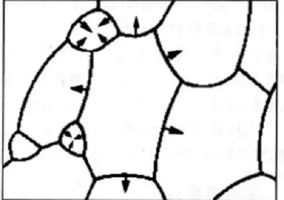
Mechanisms of Grain Growth Inhibition
The grain growth inhibitors primarily influence WC grain growth through the following approaches:
Solute Drag Effect
Principle:grain growth Inhibitor elements (e.g., V, Cr) dissolve into the WC or Co phase, adsorb at WC/Co phase boundaries or WC/WC grain boundaries, hindering atomic diffusion and grain boundary migration.
Elemental Solid Solution
Inhibitors such as VC and Cr?C? decompose during sintering, with V and Cr atoms dissolving into the WC lattice or Co binder phase.
Example: V substitutes W sites in WC (forming (V,W)C solid solution), while Cr dissolves into the Co phase (forming (Co,Cr) solid solution).
Grain Boundary Segregation
Solute atoms (e.g., V, Cr) enrich at WC grain boundaries or WC/Co interfaces, forming a “solute atmosphere.”
These segregated atoms pin grain boundaries, increasing the energy barrier for migration.
Drag on Grain Boundary Movement
When grain boundaries attempt to migrate, solute atoms must move along, but their slower diffusion rate impedes boundary motion.
Analogous to “viscous drag,” this suppresses WC grain coalescence and growth.
Applicable grain growth Inhibitors: VC, Cr?C? (primarily rely on solute drag).
Second-Phase Pinning Effect (Zener Pinning)
Principle: grain growth inhibitors form nanoscale carbide particles (e.g., (V,W)C, (Cr,W)C) that physically obstruct WC grain growth at boundaries.
Nanoparticle Precipitation
During sintering, decomposed VC or Cr?C? reprecipitate as nanoscale carbides (e.g., 5–50 nm (V,W)C particles), typically located at WC/WC or WC/Co interfaces.
Grain Boundary Pinning
Migrating boundaries must overcome the restraint of these nanoparticles, requiring additional energy.
According to the Zener equation, pinning force (F?) correlates with particle volume fraction (f) and size (r). Finer, denser particles yield stronger inhibition.
Suppression of WC Dissolution-Reprecipitation
Nanoparticles hinder WC dissolution in liquid Co and redeposition, reducing Ostwald ripening (“large grains consuming small ones”).
Applicable grain growth Inhibitors: VC (strongest pinning), Cr?C? (moderate), TaC/NbC (weaker).
Common Grain Growth Inhibitors and Their Characteristics
| Mechanism | Primary Inhibitors | Key Characteristics |
| Solute Drag | VC, Cr?C? | Hinders grain boundary migration through solute atom segregation |
| Second-Phase Pinning | VC, Cr?C? | Physically blocks grain boundaries via nanoparticle dispersion (Zener pinning) |
| Dissolution-Reprecipitation Control | VC, Cr?C? | Reduces WC dissolution in Co binder and slows atomic diffusion |
| Grain Boundary Energy Modification | TaC, NbC | Lowers grain boundary energy, enhancing high-temperature stability |
Selection and Optimization of grain growth Inhibitors
Ranking of Inhibition Effectiveness
VC > Cr?C? > TaC ≈ NbC
Key Influencing Factors
Sintering Temperature and Time:
High temperatures or prolonged sintering may weaken inhibitor effectiveness (e.g., VC particle coarsening).
Co Content
Alloys with higher Co require greater grain growth inhibitor content (due to enhanced WC dissolution in liquid Co).
Carbon Balance
Inhibitors may consume free carbon, necessitating carbon potential adjustment to avoid η-phase formation (e.g., Co?W?C).
Detailed Industrial Application Cases of Cemented Carbide Grain Growth Inhibitors
Grain growth inhibitors (e.g., VC, Cr?C?, TaC) are widely used in the cemented carbide industry, primarily in cutting tools, mining tools, and wear-resistant components. The selection of different inhibitors directly affects the alloy’s hardness, toughness, wear resistance, and high-temperature stability. Below is an in-depth analysis of several typical application cases.
Ultra-Fine Grain Cemented Carbide Cutting Tools (VC + Cr?C? Composite Inhibition)
Application Background
Requirement: High-speed cutting and precision machining (e.g., automotive engine blocks, aerospace titanium alloys) demand tools with both high hardness (>90 HRA) and chipping resistance.
Issue
Conventional WC-Co alloys have coarse grains (1–3 μm), exhibiting high hardness but low toughness, leading to edge chipping.
Solution
Ultra-fine grain cemented carbide (grain size 0.2–0.5 μm) achieved through VC (0.3–0.5 wt%) + Cr?C? (0.5–1.0 wt%) composite addition.
Inhibition Mechanism
VC: Nano-sized (V,W)C particles pin WC grain boundaries (Zener pinning), suppressing grain coalescence.
Cr?C?: Cr dissolves into the Co phase, reducing WC dissolution rate (solute drag) while enhancing oxidation resistance.
Representative Products
Sandvik GC4325: For titanium alloy machining, using VC+Cr?C? inhibition (0.3 μm grains).
Kennametal KCS10B: For stainless steel finishing, incorporating nano-VC.
Mining Cemented Carbide Drill Bits (TaC/NbC High-Temperature Inhibition)
Application Background
Requirement: Oil drill bits and tunnel boring machine cutters operate under high temperatures (>800°C) and impact loads, requiring thermal fatigue resistance and wear resistance.
Issue
Conventional WC-Co alloys experience rapid grain growth at high temperatures, reducing strength.
Solution
TaC (1–3 wt%) or NbC (1–2 wt%) addition to leverage their high-temperature stability for grain growth suppression.
Inhibition Mechanism
TaC/NbC: Form (Ta,W)C or (Nb,W)C solid solutions at high temperatures, pinning grain boundaries (Zener effect) and reducing boundary mobility.
Synergy with Co binder: Ta/Nb dissolution into Co increases liquid Co viscosity, slowing WC dissolution-reprecipitation.
Representative Products
Atlas Copco Button Bits: TaC-containing drill bits for granite drilling.
Sumitomo Electric DX Series: Oil drilling alloys with NbC for thermal stability.
Wear-Resistant Sealing Rings (Cr?C? Inhibition + Rare Earth Optimization)
Application Background
Requirement: Mechanical seals and bearing sleeves require high wear resistance + corrosion resistance (e.g., chemical pumps, seawater environments).
Issue
WC-Co suffers from selective corrosion of the Co phase in corrosive media, causing WC grain detachment.
Solution
Cr?C? (1.0–1.5 wt%) + rare earth oxides (Y?O? 0.1–0.3 wt%) composite addition.
Inhibition Mechanism:
Cr?C?: Forms (Cr,W)C particles to refine grains while improving corrosion resistance via Cr dissolution in Co.
Y?O?: Rare earth elements segregate at grain boundaries, purifying interfaces and strengthening boundary cohesion.
Representative Products
Mitsubishi Materials EX Series: Chemical pump seals with Cr?C? + rare earth modification.
Oerlikon Durit CR: Corrosion-resistant alloys with Cr?C?.
PCB Micro-Drills (Ultra-Fine VC + Sintering Process Optimization)
Application Background
Requirement: PCB micro-drills (diameter 0.1–0.3 mm) demand ultra-high precision (roundness <1 μm) and fatigue resistance.
Issue
Grain coarsening causes drill edge blunting and fracture during drilling.
Solution
Ultra-fine VC (0.2–0.4 wt%) + low-temperature sintering (1350°C, vs. conventional 1450°C).
Inhibition Mechanism
Nano-VC: Prepared via high-energy ball milling (<50 nm particles) for enhanced pinning.
Low-temperature sintering: Reduces Ostwald ripening time, preserving inhibitor efficacy.
Representative Products
Toshiba Tungaloy DLC-Coated Micro-Drills: Nano-VC inhibition technology.
TaeguTec PCB Drill: Optimized for high-layer PCBs.
Conclusion
Grain growth inhibitors in cemented carbides control grain size through solute drag and second-phase pinning mechanisms. Their selection must be optimized based on material composition, sintering processes, and performance requirements. Future trends favor nano-composite inhibitors and multi-component synergistic regulation to further enhance comprehensive material properties.
]]>
Challenges and Pain Points in the Petroleum Industry
Extreme Wear Environments
The core task of oil drilling is to penetrate complex formations, including hard rock layers such as sandstone, shale, and even granite. During this process, friction between the drill bit and rock generates significant heat, while abrasive particles like quartz sand and metal debris in the formation accelerate surface wear on equipment.
Dual Challenges of Temperature and Pressure
Oil drilling operations can reach depths of several thousand meters, where downhole temperatures may exceed 200°C and pressures can surpass 100 MPa. Conventional steel is prone to thermal expansion deformation or oxidation embrittlement under such conditions. Valve seals may soften and fail under high temperatures, leading to drilling fluid leaks and causing substantial economic losses. Additionally, frequent thermal cycling (e.g., in Arctic operations) can induce material fatigue cracking, jeopardizing equipment safety.
Balancing Cost Efficiency and Productivity
The direct consequences of equipment wear are increased maintenance costs and extended downtime. According to API standards (API Spec 7-1), traditional PDC drill bits achieve an average footage of only about 380–520 meters in formations with >40% quartz content, while each replacement operation takes 8–12 hours, severely hindering extraction progress. Moreover, component failures can trigger blowouts, oil spills, and other safety incidents, further amplifying.
Core Advantages of Cemented Carbide Wear-resistant Components
Cemented carbide is a composite material with tungsten carbide (WC) as the matrix and cobalt (Co) as the binder phase. Its performance advantages stem from its unique microstructure:
Wear Resistance
Tungsten carbide boasts a Vickers hardness of 1,600–2,400 HV, second only to diamond, enabling effective resistance to rock cutting and abrasive wear.
Stability Under High Temperature and Pressure
Tungsten carbide has an extremely high melting point (2,870°C) and maintains high strength even at elevated temperatures. The ductility provided by the cobalt binder phase further enhances the material’s impact resistance.
Corrosion Resistance
Cemented carbide exhibits strong resistance to acidic media (pH 2–12) and salt spray environments.
| Performance Metric | Traditional Material (e.g., Steel) | Cemented Carbide | Improvement Effect |
| Hardness (HRC) | 50–55 | 60–90+ | — |
| Wear Resistance | — | — | 2–5x improvement |
| Corrosion Resistance | Susceptible to acidic corrosion | Acid/alkali/oxidation resistant | 3x+ lifespan extension |
| Compressive Strength (MPa) | 800–1,200 | 3,000–6,000 | — |
| Deformation Resistance | — | — | 2–3x improvement |
| High-Temperature Stability | ≤300°C | ≤800°C | Suitable for deep wells & high-temperature oil/gas environments |
Typical Application Scenarios of Cemented Carbide Wear-Resistant Components
Cemented Carbide Bearings
Cemented carbide bearings are widely used in extreme-condition equipment within the petroleum industry. Their tungsten carbide-cobalt composite structure (HRA 85-93) combines high hardness with impact resistance. These bearings are primarily employed in critical components such as rotary steerable systems, mud pump plungers, and downhole motors. They can withstand temperatures exceeding 200°C and pressures up to 100 MPa in drilling fluids containing abrasive particles, offering a service life 3-5 times longer than traditional steel bearings.
Through gradient structure design, these bearings achieve an optimal balance between surface wear resistance and core toughness, significantly reducing unplanned tripping frequency for downhole tools. This enhancement ensures both operational safety and cost-effectiveness in ultra-deep well drilling.

Cemented Carbide Bushings
Cemented carbide bushings are extensively utilized in high-wear components of petroleum equipment such as downhole drilling tools, mud pumps, and valves. Composed of tungsten carbide or chromium carbide matrix (HRA 88-92) and densified through hot isostatic pressing (HIP) technology, these bushings demonstrate exceptional wear and corrosion resistance against sand-laden, saline drilling fluid erosion while withstanding temperatures of 150-300°C and acidic environments.
The surface-gradient alloying design enhances galling resistance while maintaining core toughness, extending bushing service life by 2-4 times in directional drilling tools. This innovation effectively reduces stuck pipe risks and minimizes maintenance downtime, ensuring continuous operation under complex deep-well conditions.

Cemented Carbide Valve Seats & Sealing Components
In petroleum extraction, the valve balls and seats of oil well pumps serve as critical sealing elements. Conventional materials are prone to failure due to wear, corrosion, or high-pressure impact, necessitating frequent shutdowns for replacement.
Cemented carbide valve seats (e.g., YG series) overcome these limitations with:
1.Superior hardness (HRC 90+), delivering 3× greater wear resistance
2.Extended service life (2-3× longer than standard materials) when paired with carbide valve cores
3.Significant reduction in downtime-related costs
This engineered solution ensures reliable performance in demanding pumping applications while optimizing operational efficiency.

Cemented Carbide Nozzles
Hardened carbide nozzles for high-pressure abrasive jet technology significantly enhance formation cutting efficiency, making them ideal for deep reservoir extraction with wear resistance far exceeding conventional materials.
The innovative spiral-flow-channel nozzles feature gradient structure design with:
1.Surface WC content up to 94wt% for extreme wear resistance
2.Core cobalt content of 8-10wt% for optimal toughness
This balanced composition achieves both superior surface durability and bulk material integrity.
1.The advanced fluid dynamics optimization:
2.Increases drilling fluid velocity by 30%
3.Effectively removes downhole cuttings
4.Maintains stable performance in extreme downhole conditions
Cemented Carbide Centralizers
Cemented carbide centralizers are used for casing cementing. The spiral rib design improves displacement efficiency, making them suitable for deviated and horizontal wells, with strong impact resistance and low friction coefficient.
The centralizers support the casing through rigid or elastic structures, reducing eccentricity caused by wall friction, significantly improving casing centralization—especially in deviated and horizontal wells. For example, the spiral rib design reduces casing running resistance through its streamlined structure and uses rotational action to condition the wellbore, ensuring gauge protection.
Conclusion
The development of ultra-fine grain cemented carbide (grain size <0.5μm) and novel binder phases (such as nickel-based alloys) will elevate material performance to new heights. Furthermore, the application of intelligent monitoring systems (e.g., embedded wear sensors) enables real-time prediction of component lifespan, driving the petroleum industry toward its goal of “zero unplanned downtime.” Cemented carbide wear-resistant components are not merely vessels of technology, but cornerstones for the sustainable development of the petroleum industry.
From penetrating ten-thousand-meter rock formations to resisting deep-sea corrosion, cemented carbide wear-resistant components have written a revolutionary chapter in the petroleum industry with their unique combination of “strength and resilience.” They are not only powerful tools for extending equipment lifespan but also critical enablers for reducing carbon emissions and achieving green extraction. Looking ahead, with growing global energy demands and technological advancements, cemented carbide is destined to shine even brighter in the petroleum sector.
]]>
The primary functions of binders in cemented carbide manufacturing
In the powder metallurgy of cemented carbides, binders (also called forming agents) play critical roles, including:
Improving Powder Flowability
Reduces interparticle friction, enabling homogeneous mold filling and uniform compaction.
Prevents powder segregation (e.g., separation of WC and Co).
Enhancing Green Strength
Provides sufficient “green strength” to prevent cracking or edge chipping during handling or demolding.
Minimizes elastic aftereffects (post-compaction expansion).
Lubricating the Mold
Reduces friction between powder and die walls, lowering compaction pressure and extending mold life.
Improves surface finish and minimizes defects (e.g., delamination, cracks).
Facilitating Debinding
Must be fully removable (via thermal decomposition or dissolution) before sintering to avoid carbon residue or impurities that degrade alloy properties.
Performance Requirements for Binders
The binder must possess the following characteristics:
Excellent Compatibility
Uniformly mixes with WC-Co powders without agglomeration or sedimentation.
Chemically inert to powders (e.g., no oxidation of cobalt).
Suitable Melting Point and Viscosity
Melting point must align with compaction temperatures (typically room temperature to 100°C) to ensure:
Liquid-phase homogeneity during mixing.
Solid-phase strength during pressing.
Too high moderate viscosity leads to impedes powder flow.
Too low moderate viscosity leads to insufficient binding force.
High Binding Capacity and Lubricity
Binding capacity: Ensures green strength (flexural strength typically ≥5 MPa).
Lubricity: Reduces compaction pressure (e.g., from 600 MPa to 400 MPa).
Controlled Debinding Behavior
Broad debinding temperature range (e.g., 150–500°C) to prevent cracking from rapid volatilization.
Low carbon residue after debinding (<0.1%) to avoid disrupting alloy carbon balance.
Environmental and Safety Compliance
Non-toxic, low volatility (e.g., water-soluble PEG outperforms solvent-based rubber binders).
Meets industrial emission standards (e.g., sulfur- and chlorine-free).
Cost-Effectiveness
Low-cost and readily available (e.g., paraffin wax is more economical than rubber).
Recyclable or easy to dispose of (e.g., PEG can be water-washed and recovered).
Types of Binder
When manufacturing cemented carbide products, selecting the right binder is crucial for quality and efficiency. Here’s a detailed comparison of the three most common binder types to help you make the best choice for your application.
Paraffin Wax

Characteristics:Composition: Hydrocarbon-based, solid at room temperature with low melting point (50-70°C)
Best for: Small, simple-shaped carbide products
Advantages:
Excellent lubricity reduces die friction
Low debinding temperature (200-400°C) simplifies processing
Cost-effective and readily available
Limitations:
Lower green strength (prone to cracking)
Potential carbon residue during high-temperature debinding
Temperature-sensitive – requires dry storage
Pro Tip: Ideal for mass production of standard inserts where cost is key.

PEG (Polyethylene Glycol)
Characteristics:Composition: Water-soluble polymer with adjustable molecular weight (PEG-2000/4000)
Best for: Complex-shaped tools and precision molds
Advantages:
Higher green strength for intricate shapes
Water-soluble – enables aqueous pre-debinding
Minimal carbon residue
Limitations:
Hygroscopic – requires humidity control
Narrow debinding window (200-300°C)
More expensive than paraffin
Pro Tip: The go-to choice for premium cutting tools requiring precision.

Rubber (SBR, etc.)
Characteristics:Composition: Polymer elastomer requiring organic solvents (e.g., acetone)
Best for: Large, high-density components like rolls and mining tools
Advantages:
Highest green strength
Excellent elasticity prevents cracking
Limitations:
Challenging debinding (500°C+)
Potential sulfur contamination
Environmental concerns with solvents
Highest cost
Pro Tip: Reserved for specialized applications where extreme strength is critical.
Compatibility Principles Between Binders and Wet Milling Media
Paraffin Wax
- Requires organic solvents (e.g., ethanol, acetone)
- Limited solubility in ethanol alone – heating often needed
Recommended Medium: Ethanol + 10-20% acetone (enhances solubility)
PEG (Polyethylene Glycol)
- Excellent water solubility
- Requires oxidation protection for cobalt
Recommended Medium: Deionized water + 0.5% antioxidant (e.g., oxalic acid)
Rubber Binders
- Only soluble in strong organic solvents
Recommended Medium: Pure acetone (requires sealed system to prevent evaporation)
Performance Comparison of Three Major Binder Systems
Binding Strength
Rubber binders provide the highest strength due to their polymer chain structure, making them suitable for large compacts. PEG offers moderate strength ideal for complex geometries, while paraffin wax has the lowest binding strength as it relies solely on physical bonding.
Debinding Process
Paraffin wax can be removed at relatively low temperatures between 200 to 400°C, though carbon balance must be carefully controlled. PEG requires aqueous pre-debinding followed by thermal cycling, but is sensitive to moisture. Rubber binders demand high-temperature pyrolysis above 500°C and carry risks of sulfur contamination.
Residue Effects
Paraffin may leave carbon residues that affect the WC/Co ratio, requiring adjustment of carbon potential during sintering. PEG leaves virtually no residue, making it excellent for high-purity alloys. Rubber can leave sulfur residues that reduce the alloy’s corrosion resistance.
Economic Considerations
Paraffin wax has the lowest initial cost but may incur additional expenses for carbon management. PEG provides the best value for precision components and mass production. Rubber is the most expensive option and is only justified for specialized heavy-duty applications.
Selection Summary
For cost-sensitive production where simple processes are preferred, paraffin wax is suitable but requires careful control of dimensional stability during debinding. When high precision and environmental considerations are priorities, PEG is the optimal choice though it needs humidity-controlled storage. Rubber binders are reserved for applications requiring maximum strength and large components, provided that high-temperature debinding equipment is available.
Modern developments are creating hybrid binder systems that combine the advantages of these materials, such as PEG’s performance with paraffin’s cost benefits through advanced formulation techniques.
]]>Process Measures to Reduce Machining Deformation
Reducing Residual Stress in Blanks
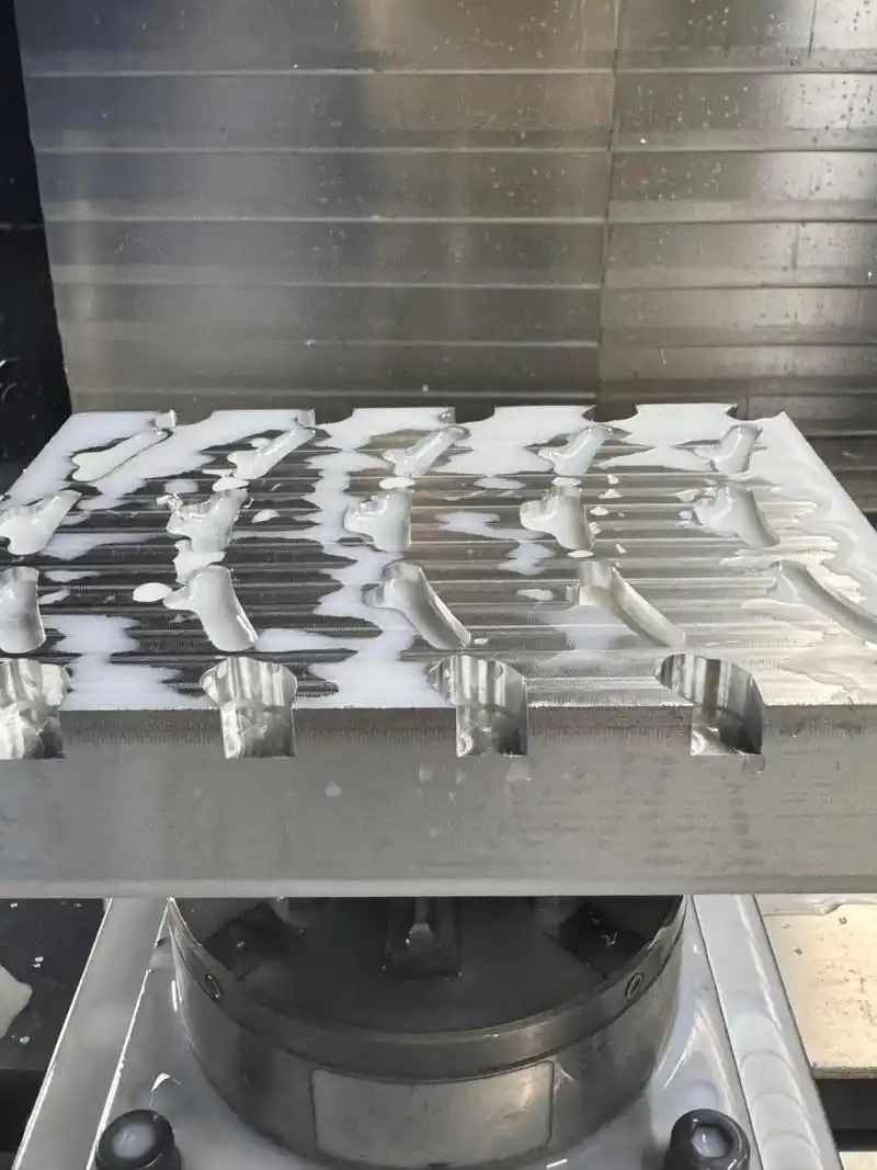
Natural or artificial aging, as well as vibration treatment, can partially eliminate residual stresses in blanks. Pre-machining is also an effective method. For bulky blanks with excessive stock allowance, post-machining deformation tends to be significant. By pre-machining to remove excess material and balance stock allowance, subsequent machining deformation can be reduced. Additionally, allowing the pre-machined blank to rest helps release residual stresses.
Improving Tool Cutting Performance
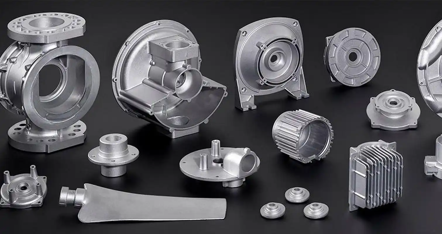
Tool material and geometric parameters significantly influence cutting forces and heat generation. Proper tool selection is crucial for minimizing part deformation.
Optimizing Tool Geometry
Rake Angle:
A larger rake angle (while maintaining edge strength) enhances cutting sharpness, reduces chip deformation, improves chip evacuation, and lowers cutting forces and temperatures. Negative rake angles should be avoided.
Clearance Angle:
The clearance angle directly affects flank wear and surface finish. For rough milling with heavy loads and high heat, a smaller clearance angle improves heat dissipation. For finish milling, a larger clearance angle reduces friction and elastic deformation.
Helix Angle:
A higher helix angle ensures smoother milling and reduces cutting resistance.
Lead Angle:
A smaller lead angle improves heat dissipation and lowers average cutting zone temperatures.
Enhancing Tool Structure
Reducing Teeth Count & Increasing Chip Space:
Aluminum’s high plasticity demands larger chip pockets. Tools with fewer teeth and wider gullets are preferred.
Precision Edge Honing:
The cutting edge roughness should be below Ra = 0.4 μm. Lightly honing new tools with a fine stone removes burrs and micro-serrations, reducing heat and deformation.
Strict Wear Control:
Tool wear increases surface roughness, cutting temperature, and part deformation. Wear limits should not exceed 0.2 mm to prevent built-up edge. Workpiece temperature should stay below 100°C to avoid distortion.
Optimizing Workpiece Fixturing
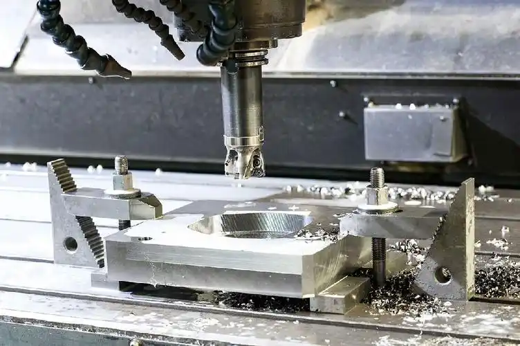
For thin-walled aluminum parts with low rigidity:
Axial Clamping for Bushings
Radial clamping (e.g., 3-jaw chucks) causes post-machining deformation. Instead, use a threaded mandrel inserted into the part’s bore, secured axially with a endplate and nut to maintain precision during OD machining.
Vacuum Chucks for Thin Plates
Uniform clamping force distribution paired with light cuts minimizes distortion.
Filling Method
Fill hollow parts with a low-melting filler (e.g., urea-potassium nitrate melt) to enhance rigidity during machining. Dissolve the filler post-process in water/alcohol.
Strategic Process Sequencing
High-speed machining with large stock or interrupted cuts may induce vibration. A typical CNC process flow:
Roughing → Semi-finishing → Corner Cleaning → Finishing
For high-precision parts, repeat semi-finishing before final passes. Post-roughing natural cooling relieves stresses. Leave 1–2 mm stock after roughing; maintain 0.2–0.5 mm uniform allowance in finishing to ensure stability, reduce deformation, and achieve high surface quality.
Operational Techniques to Minimize Machining Deformation
In addition to the aforementioned causes, operational methods play a crucial role in controlling deformation during aluminum part machining.
Symmetrical Machining for Large Stock Parts
For better heat dissipation, use alternating symmetrical machining. Example: A 90mm plate machined to 60mm achieves 0.3mm flatness when processed in alternating passes versus 5mm with consecutive machining.
Layered Machining for Multi-cavity Parts
Machine all cavities layer-by-layer simultaneously to ensure uniform stress distribution, preventing deformation from uneven forces.
Optimized Cutting Parameters
Adjust depth of cut (ap) with corresponding feed rate and spindle speed increases in CNC high-speed milling to balance productivity and reduced cutting forces.
Strategic Tool Path Selection
Use conventional milling for roughing (maximum removal rate) and climb milling for finishing (better surface quality with progressive chip thickness reduction).
Thin-wall Fixturing Technique
Before final passes, briefly release and reapply minimal clamping force to allow natural recovery, applying force along the part’s most rigid direction.
Cavity Machining Method
Avoid direct plunging; pre-drill or use helical entry paths to prevent chip packing and tool breakage.
Conclusion
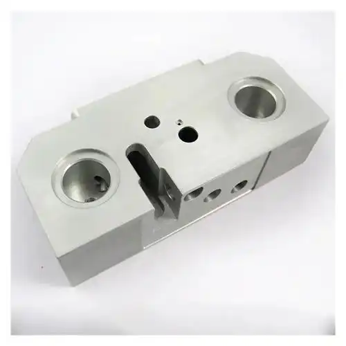
Aluminum part deformation stems from material properties, geometry, and processing conditions, primarily involving?blank residual stresses,cutting forces/heat,and clamping stresses.The integrated application of these process optimizations and operational techniques significantly reduces deformation, enhances precision and surface quality, providing reliable technical support for production.
]]>They can be usefully used for finishing stands of high-speed wire rod mills (up to 120 m/s),precision rolling of rebars, alloy steels, and non-ferrous metals, and high-reduction passes where wear resistance is critical
Practical condition
Located in Guangdong Province, A metal production company commissioned its high-speed wire rod mill (with an annual capacity of 1.2 million tons of φ5.5~φ16mm wire rods) in December 2010 to enhance production efficiency and meet market demands.
The mill primarily consists of five key components: roughing mill, intermediate mill, pre-finishing mill, and finishing mill. The roughing mill features a single-line configuration with 5 stands (φ550×5) arranged in horizontal-horizontal-vertical-horizontal-vertical (HHVHV) pattern. The intermediate mill comprises 8 stands (φ550×2+φ450×4+φ350×2) with all-horizontal rolls. The pre-finishing mill has 8 stands (dual-line, 4 stands per line) configured as cantilever-type two-high mills (φ285×4×2) with alternating horizontal/vertical arrangement. The finishing mill contains 20 stands (dual-line, 10 stands per line) of cantilever-type two-high mills (gang-driven, φ228×5+φ170×5) in 45° top-cross configuration.
Due to humid climatic conditions, the mill encountered roll ring explosions caused by moisture-induced rusting of roll rings and taper sleeves. A technical task force was established to identify root causes and implement corrective measures to ensure stable production.

Production Process Overview
The manufacturing process flows as follows:
1.After single-pass rolling in the roughing mill, the billet undergoes head/tail cropping at #1 flying shear (with emergency scrap chopping capability), then diverges into dual lines via a distributor for intermediate rolling under micro-tension control.
2.Following intermediate rolling, the stock passes through #2 flying shear for cropping before entering pre-finishing mill, where pneumatic vertical loopers enable twist-free, tensionless rolling for precise dimensional control.
3.Pre-finished stock undergoes water cooling and #3 flying shear cropping before entering finishing mill. Emergency shutoff shears activate to prevent further stock entry during malfunctions.
4.The 45° top-cross finishing mill employs gang-driven tungsten carbide roll rings for twist-free micro-tension rolling, achieving final dimensions at speeds up to 95m/s for φ5.5~7mm products.

Root Cause Analysis of Roll Ring Failures
The cost-optimized tungsten carbide roll rings exhibited these failure mechanisms:
Ambient humidity caused rust corrosion at roll ring/taper sleeve interfaces
Thermal fatigue from cyclic temperature variations (Fig.1) accelerated crack propagation
Insufficient cooling exacerbated thermal stresses (increased ΔT)
Improper assembly caused taper sleeve seizure
Brittle material properties increased handling damage risks
Technical Improvements & Process Controls
Material Selection Optimization
The YGR-series roll rings were selected for their Ni/Cr-enhanced properties:
1.Superior oxidation resistance (700-1000℃)
2.Improved acid corrosion resistance (pH≤7.2)
3.Enhanced thermal crack resistance
4.Optimal hardness-toughness balance across mill stands
Cooling System Enhancements
Implemented strict water management protocols:
1.Flow rates: 18-25m3/h per stand (slot-width dependent)
2.Pressure maintenance: 3-7bar at nozzles
3.Monthly water quality testing for particulate control
Dedicated pipe alignment inspections during maintenance
Optimum Rolling Tonnage
Established safe grinding thresholds at 0.2-0.4mm crack depth:
Stands 1-4: 1,800-2,500 tons
Stands 5-8: 1,500-2,000 tons
Stands 9-10: 600-1,000 tons
Precision Assembly Standards
Mandatory surface cleaning before assembly
Prohibited impact mounting methods
Individual roll storage in partitioned containers
Strict taper sleeve inspection/rejection criteria
Conclusion
The comprehensive improvement program addressing material selection, cooling optimization, production control, and precision maintenance successfully resolved roll ring failures, achieving sustained operational stability. This methodology provides valuable reference for similar applications.
Key Recommendations
1.Select roll ring grades considering environmental factors
2.Maintain rigorous cooling water quality standards
3.Adhere to prescribed rolling tonnage limits
4.Implement precision handling and maintenance protocols
]]>Basic Definitions of Positive and Negative Rake Angle Tools
Positive Rake Angle Tool
A positive rake angle tool refers to a turning tool where the front face is inclined toward the interior of the workpiece relative to the cutting point, resulting in a positive rake angle (typically +5° to +15°). Its structural characteristic is a relatively sharp cutting edge, with a smaller contact area between the front face and the chip.
Negative Rake Angle Tool
A negative rake angle tool, on the other hand, has a front face inclined outward from the workpiece relative to the cutting point, resulting in a negative rake angle (typically -5° to -10°). Its structural feature is a blunter cutting edge, with a thicker and more robust tooltip.
Advantages and Disadvantages of Positive and Negative Rake Tools
Positive Rake Angle Tool
Advantages:
Lower Cutting Forces: A positive rake angle allows smoother chip flow and reduces deformation, decreasing main cutting forces by 15–25%.
Better Chip Evacuation: Shorter chip-tool contact length reduces built-up edge formation.
Suitable for Finishing: Minimizes vibration, enabling better surface finish (Ra < 1.6 μm).
Disadvantages:
Lower Tooltip Strength: The positive geometry reduces material support, making the tool prone to chipping in interrupted cuts or hard materials.
Poor Heat Dissipation: Smaller chip-tool contact area limits heat transfer, accelerating crater wear at high speeds.
Shorter Tool Life: Typically 60–70% of negative rake tools under the same conditions.
Negative Rake Angle Tool
Advantages:
High Tooltip Strength: The negative angle creates a “support wedge,” improving impact resistance by >50%.
Superior Heat Dissipation: Larger chip-tool contact area enhances heat conduction, reducing cutting temperatures by 15–30°C.
Multi-Sided Usability: Often designed with double-negative angles, allowing flipping for extended use.
Limitations:
Higher Cutting Forces: Negative rake increases chip deformation, raising main cutting forces by 20–30%.
Greater Power Demand: Requires 15–20% more motor power from the machine tool.
Vibration Risk: Prone to chatter in long overhang machining due to increased cutting forces.
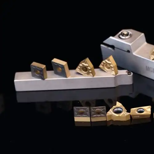
Experimental Comparison
The following systematic experiment compares the performance of carbide positive and negative rake tools under different machining conditions, providing practical insights for tool selection.
Experimental Design
1.Materials & Equipment:
Positive rake tool (+8° rake angle)
Negative rake tool (-6° rake angle)
Both use YG8 carbide substrate with TiAlN coating and 0.4 mm nose radius.
2.Workpiece:45# steel (Φ50×200 mm), quenched and tempered to HRC 28–32.
3.Machine:CA6140 lathe with 3-jaw chuck and tailstock center.
4.Measurement Instruments:
Surface roughness tester (Mitutoyo SJ-210)
Electron microscope (OLYMPUS DSX510)
Cutting force dynamometer (Kistler 9257B)
Infrared thermometer (Fluke Ti400)
5.Parameters
Fixed: Depth of cut (ap = 1 mm), feed rate (f = 0.15 mm/rev).
Variable: Cutting speed (v = 60–180 m/min).
Three repetitions per condition for reliability.
Results & Analysis
Tool Wear & Life Comparison
Using flank wear VB = 0.3 mm as the failure criterion:

Negative rake angle tools demonstrate significantly longer service life, exceeding positive rake tools by an average of 50-70%. Analysis of wear patterns reveals that positive rake tools primarily fail through crater wear on the rake face and tooltip chipping, whereas negative rake tools exhibit more uniform flank wear, demonstrating superior fracture resistance.
Cutting Force Comparison

The data shows that under all tested cutting speeds, negative rake tools generate significantly higher principal cutting forces than positive rake tools, with an average increase of approximately 17%. This is attributed to the negative rake design’s larger contact area between the tool’s rake face and chips, as well as intensified cutting deformation. Notably, while cutting forces for both tool types decrease with increasing cutting speed, the difference ratio remains essentially stable.
Cutting Temperature Comparison
Results indicate that negative rake tools maintain consistently lower cutting temperatures than positive rake tools, typically by 15-25°C. This thermal advantage primarily stems from the negative rake design’s enhanced tooltip strength and improved heat dissipation capacity. The temperature difference becomes particularly pronounced during high-speed cutting (v>120m/min), reaching approximately 30°C.
Surface Quality Evaluation
Surface roughness serves as a critical indicator of machining quality. At a feed rate of f=0.15mm/rev, measurements show:
Positive rake tool surface roughness (Ra): 1.6-2.0μm
Negative rake tool surface roughness (Ra): 1.2-1.5μm
Electron microscope observations reveal that surfaces machined with negative rake tools exhibit more uniform texture patterns with fewer burrs and vibration marks. This improvement results from the negative rake design’s enhanced system rigidity that reduces cutting vibrations. Furthermore, negative rake tools maintain more stable tooltip geometry during machining, avoiding the surface quality degradation caused by micro-chipping that often occurs with positive rake tools.
Conclusions
1.While carbide negative rake tools show slightly inferior performance in cutting force, they demonstrate clear advantages in cutting temperature control, surface quality, and tool life.
2.The performance advantages of negative rake tools become more pronounced at higher cutting speeds, making them particularly suitable for modern high-speed machining requirements.
3.Positive rake tools excel in reducing cutting forces and are better suited for machining systems with limited rigidity.
4.Optimal tool angle selection should comprehensively consider multiple factors including workpiece material, machine tool conditions, and specific machining stages.
]]>
Physical Nature of Coating Thickness and Functional Realization
The physical essence of coating technology lies in modifying interfacial properties of the substrate via surface engineering. For rotating tools like drills, coatings must simultaneously reduce friction, enhance surface hardness, and inhibit thermal conduction. When coating thickness ranges from nanometers to micrometers, significant size effects emerge in mechanical properties. Experimental data shows that TiN coatings reach peak microhardness (≈2300HV) at 2-3μm thickness; further increases reduce hardness due to accumulated residual stress. This stress heterogeneity creates preferential paths for microcrack propagation during drilling, especially under interrupted cutting conditions, where excessively thick coatings are prone to delamination.
Thermal barrier effects are vital, but thermal conductivity does not scale linearly with thickness. Finite element simulations reveal that beyond 5μm, AlCrN coatings show diminishing thermal resistance gains. Excessive thickness may impede heat dissipation, intensifying thermal stress concentration in high-speed machining.
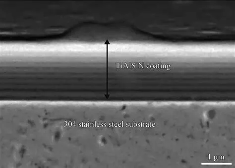
Dynamic Evolution of Cutting Edge Geometry
Drill edge sharpness directly affects chip evacuation and force distribution. The “rounding effect” during deposition causes exponential growth in edge radius with thickness. For DLC coatings increasing from 1μm to 3μm, edge radius swells from 3.2μm to 8.7μm, raising cutting resistance by 23%. This geometric dulling is pronounced in ductile materials—aluminum alloy tests show a 15% rise in chip buildup probability per micrometer increase in edge radius. Paradoxically, moderate dulling suppresses edge chipping in brittle materials, highlighting the need for material-specific thickness optimization.
Coating thickness impacts flute hydrodynamics, often overlooked. 3D flow simulations show that when coating exceeds 12% of flute depth, secondary chip flow intensifies, causing blockages. In deep-hole drilling, this exacerbates radial vibration, increasing borehole deviation. A German toolmaker reduced straightness errors by 40% by decreasing TiAlSiN thickness from 4μm to 2.5μm.
Multiscale Correlation of Interface Failure Mechanisms
Coating-substrate bond strength does not monotonically change with thickness. Interface energy tests reveal a 30% strength drop when CrN exceeds ~4μm, due to lattice mismatch stress accumulation. This weakening is perilous under cyclic loading, with failures originating at nanoscale voids. Gradient transition layers enhance critical thickness—inserting a 50nm Ti interlayer between WC-Co and TiCN boosts critical thickness from 3.2μm to 5.1μm.
Cyclic loading reveals time-dependent failure. Accelerated life tests show 3μm AlTiN coatings reduce crack growth by 67% after 10? impacts, benefiting from crack closure effects. Beyond 2×10? cycles, thicker coatings exhibit larger spalling areas, indicating an optimal thickness for fatigue life. This non-monotonic relationship demands precise service life predictions.
Implicit Links to Machining Precision and Surface Integrity
Coating thickness has dual impacts on precision. In micro-hole drilling, a 2μm thickness deviation causes 0.8-1.2% diameter variation. A Japanese firm’s adaptive coating technology deposits 1.5μm at the tip and 2.2μm at margins, controlling diameter?floating?to 0.3%. Such differential designs surpass conventional uniform coatings.
Residual stress in workpieces couples with coating thickness. XRD analysis shows a drop from -450MPa to -280MPa when thickness increases from 1μm to 3μm, potentially reducing dimensional stability. However, thicker coatings reduce heat-affected zones by 35%, critical for aerospace aluminum.
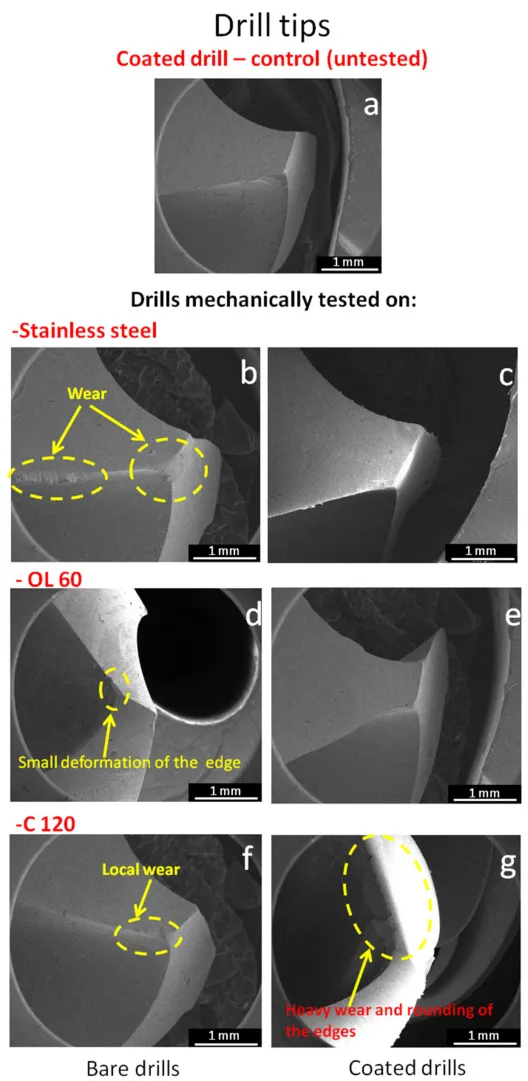
Economic Considerations and Technological Trends
Coating cost scales with thickness squared, but lifespan gains have inflection points. An automotive plant found that increasing TiAlN from 2μm to 3μm raised costs by 18% while only improving life by 12%, resulting in negative ROI. However, nano-multilayered 2.5μm coatings outperformed 3μm by 25%, indicating that thickness alone is suboptimal.
Future coatings will feature intelligent thickness control. Digital twin-based optimization systems are operational, adjusting parameters via real-time force/temperature feedback. A German AI system predicts optimal thickness in 48 hours, enhancing performance by >30%. Dynamic adaptation may revolutionize traditional thickness determination.
Conclusion
Coating thickness orchestrates a precision symphony in drill performance, where each parameter adjustment triggers cascading effects. Modern engineers must transcend empirical selection, establishing multi-physics digital design paradigms. Future breakthroughs may lie in self-sensing smart coatings with dynamic thickness adjustment, potentially sparking a new revolution. In this era of precision and intelligence, mastering coating thickness will benchmark a nation’s advanced manufacturing prowess.
]]>
